Intro:
This module is a tiny little processor for control voltages: the Control Voltage Inverter (CVI).
As its name already says it works as an inverter for control voltages, like LFO- or ADSR-signals to generate additional effects by the usage of the inverted phase of the processed control voltage in effect modules.
Frontend:
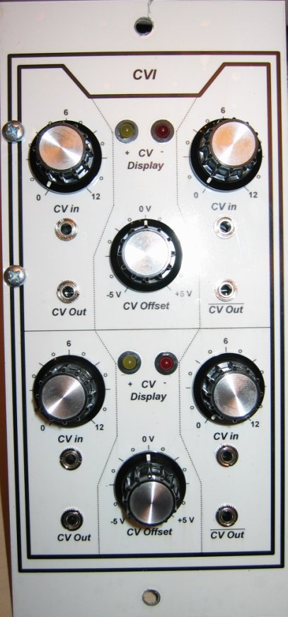
Each inverter module has two level potted 'CV in' connectors which are mixed and lead to the corresponding inverter. The polarity and the amplitude of the sum of the input signals is displayed by two LEDs (CV Display).
A fixed voltage between -3 and +3 Volt can be added by the 'CV Offset' pot for a zero calibration for instance (both LEDs are dark).
The mixture of input and offset is provided at corresponding output connectors an an inverted and non inverted form.
Hint: This module processes control voltages and is not controlled by them.
Circuit:
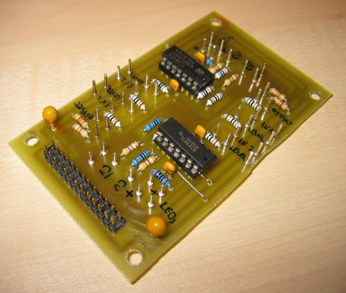
This module consist of simple opamp based mixer and inverter circuits made of TL06x opamps. I do not present a circuit here though because it belongs to the book MSS2000 from HaJo Helmstedt, so please refer to it.
Board of the CVI module:
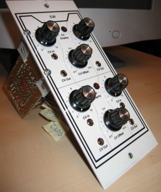
Complete module:
Sound example: Leslie: An LFO sinus controls two VCAs, one time inverted.
Reproduction hints:
None.