Click to enlarge
Click to enlarge

Click to enlarge
Click to enlarge
Click to enlarge

Click to enlarge | Click to enlarge | Click to enlarge | Click to enlarge | Click to enlarge |
|
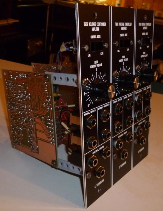
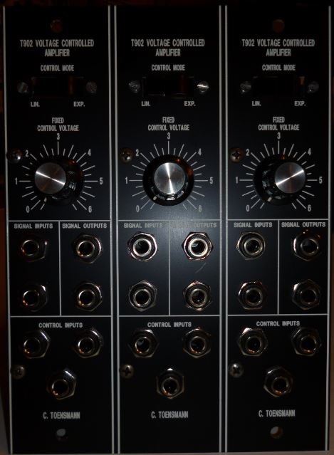
VCA On top you find a switch to select the so called "Control Mode" where the response of the VCA to the control voltages provided to the module can be selected. The (LIN.)ear behaviour means the attenuation of the module follows the control voltages quite linear, and the (EXP.)onential behaviour means an exponential response. The attenuation lowers quite fast at increasing control voltages, then the reaction gets slower when attenuation approaches "open" status. The FIXED CONTROL VOLTAGE knob adds a voltage to the control voltage node within the module (see circuit description below), and if no CV is provided the VCA can be opened or closed manually. If control voltages range in negative volts they can be shifted up with this potentiometer. Below the FIXED CONTROL VOLTAGE knob there are blocks with connectors for input and output signals. There are two of them for input and two for output. Each input connector is connected to one of two opposite sides of input differential amplifiers (see circuit description below), meaning the phase of one side ist inverted related to the other side. The same on the output side. The two output connectors belong to phase inverted outputs of the output differential amplifier (see circuit description below). This leads to the effect, that a signal on I+ can be obtained at O+ phase identical and O- phase inverted. This is interesting for LFO processing. On the other hand similar inputs at I+ and I- might result into phase cancellation, so be careful in mixing signals. In general: I+ <= O+, I+ <= /O- and vice versa. Last but not least you find the three CONTROL INPUT connectors on the front panel. Here you can plug in the CVs of ADSRs, LFOs or whatever. The CVs are mixed and control the attenuation behaviour of the VCA. |
|
 Click to enlarge |
 Click to enlarge |