Introduction:
This is the first module of the second Moog (TM) Modular Oscillator topology (921A/B), the 921A Oscillator Driver. In contrast to the 901 oscillator architecture this "control voltage pre-processor" does not contain an expo converter; it just converts incoming control voltages (-6 to +6V) for oscillator frequency control and pulse width modulation into voltages which are expected by the 921B Oscillator circuit to work properly. Both control functions can be done manually also with corresponding pots.
Additionally the oscillator frequency control can be changed from 1V / oct (OCTAVE) to 2V / oct (SEMITONE) behaviour; I can't imagine any practical or musical use currently.
The T921A oscillator driver is laid-out to drive up to three 921B Oscillators.
Circuit:
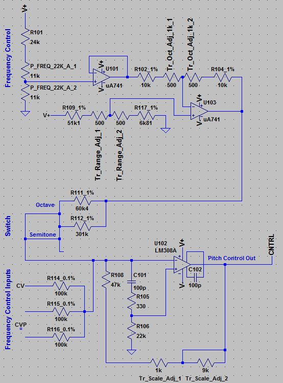
Frequency Control: Clicking the schema means accepting the disclaimer on page bottom!
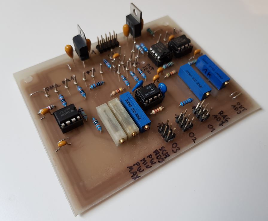
Three frequency control input jacks (6.3mm, R114 - R116) are mixed with a voltage provided by the frequency control pot of the front panel. The impact of turning the knob is adjusted by the OCTAVE_ADJUST multiturn trim. An offset voltage can be added to this with the RANGE_ADJUST multiturn trim to achive zero alignment at middle pot position.
The manual frequency control can be set to 1V / oct - behaviour be setting the switch to OCTAVE position. This means turning the frequency control knob from e. g. 0 to 1 or from 1 to 2 increases the output frequency of the attached oscillators by 1 octave. Switching to SEMITONE increases the oscillator frequencies by half an octave with the same turning. This is done by setting R111 in parallel to R112 to decrease total resistance for the OCTAVE case and vice versa.
The resulting control voltage mixture ist amplified by U102. The overall amplification can be adjusted by the SCALE_ADJUST multiturn trim within the feedback loop of the opamp.
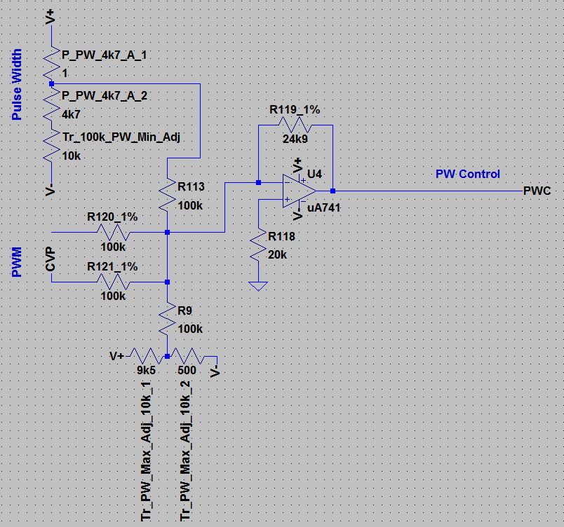
Pulse Width Control: Clicking the schema means accepting the disclaimer on page bottom!
Two pulse with modulation input jacks (6.3mm, R120 - R121) are mixed with the output voltages of the limiting voltage deviders PW_MIN_ADJUST and PW_MAX_ADJUST. The total amplification of the pulse with control voltage mix is fix (see below).
Please note: The original circuit of the Moog (TM) Service Manual does not make clear that the FREQUENCY control pot has to be connected with low side to +V and high side to GND to work properly.
Setup and Test:
The 921A adjustment procedures of the Moog (TM) Modular Service Manual can be simplified to two formulas:
- FREQUENCY CONTROL: Internal_U_out = - 0.5 x External_U_in ==> +4V in = -2V out, -1V in = +0.5V out and so on (frequency knob at position "0")
- PULSE WIDTH MODULATION: Internal_U_out = - 0.25 x External_U_in - 1.5V (width knob at 50% position) ==> +2V in = -2V out, -1V in = -1.25V out and so on
Part replacements:
- The SCALE_ADJUST trim should be a 10k type instead of 2k of the original circuit, as the adjustment range can be insufficiont with 2k.
- I did not provide an internal PWM connection, just an internal frequency control provided by a TCP3A module.
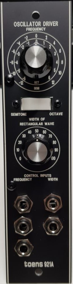
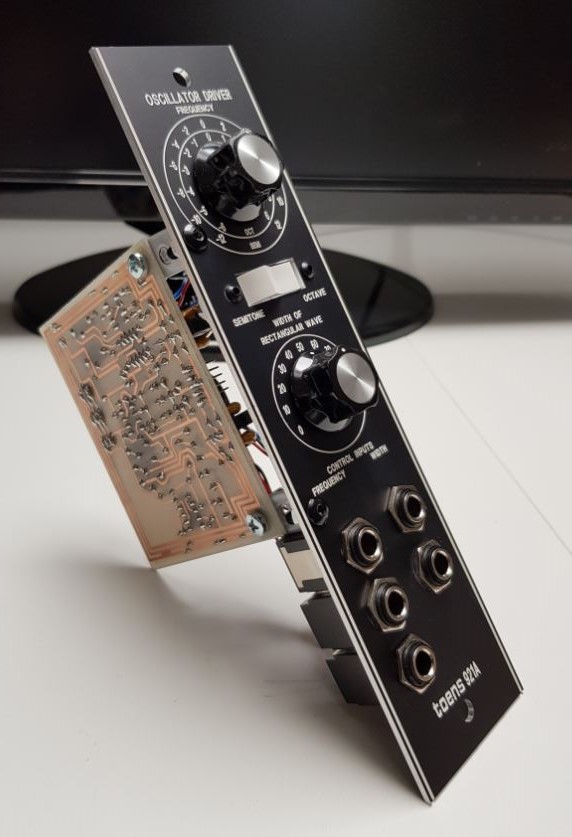
Frontend:
- FREQUENCY control pot: Curious. One can adjust octaves here. And OF COURSE one octave consists of two semi octaves, so the two concentric scales are a redundant information for the same issue.
- SEMITONE/OCTAVE switch: Changes behaviour of the manual FREQUENCY control pot. The scales of the pot are misleading, as the semitone scale changes to +/-3 octaves, not to +/-12 semitones.
- PULSE WIDTH manual control: Adjusts square wave form of attached oscillators from needle to symmetrical form and vice versa.
- Three FREQUENCY CONTROL INPUTS: CV inputs for frequency control.
- Two PULSE WIDTH CONTROL INPUTS: CV inputs for pulse with modulation.
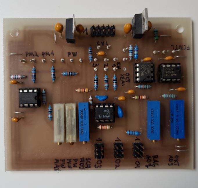
T921A Module
|
|
| 
|
| 
|