|
|
Well, at the end I did it. In times of MIDI applications and software sequencers there is no need for a hardware sequencer module, I said. But I was wrong. I played around with a 960 of a friend, and then I knew that I want a sequencer.
As this is a System 55 clone project, it had to be at least a kind of 960 clone. But looking at the original circuit diagrams I decided to reimplement the whole logic in a microcontroller based design. The 960 does not affect any sound creation or sound processing, just contains control functions and logic, so I decided to clone just the functions, not the interior.
And using a microcontroller design offered a whole bunch of additional features, which the original can't deal with, as row selection without the need of a sequential switch, MIDI capabilities and one of my personal favorites, the wonderful ratchet effect.
And this is just the beginning of it. The T960 provides an ISP interface to upload any additional feature your weird fantasy can create, so the T960 is a huge playground for synthesizer control.
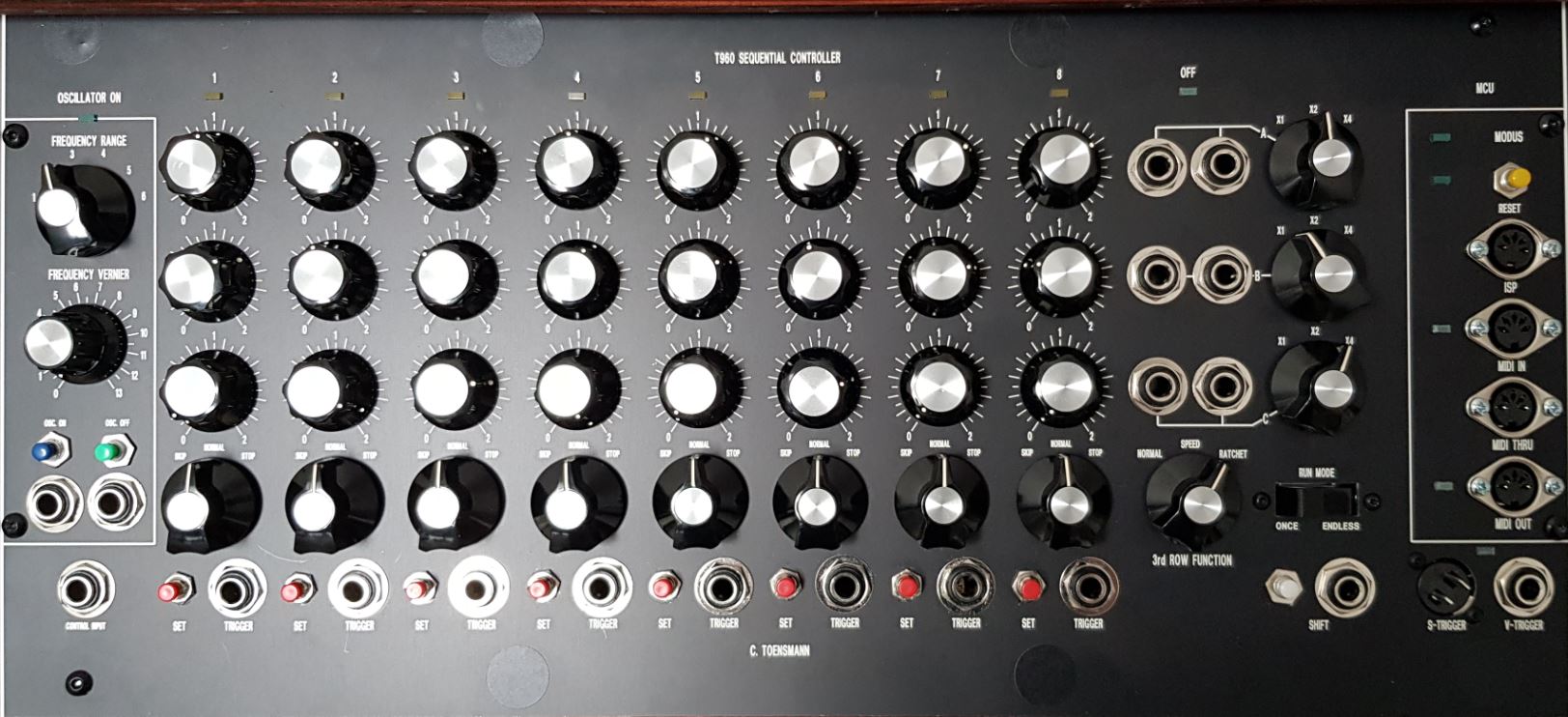
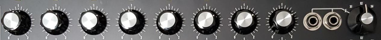
Basically it is, like the original, a 3 row 8 step sequencer. The voltage range of each step of a row is defined with a range selection, where the basic maximum voltage of 2V is multilpied by one, two or four, so a maximum of 8V can be obtained from a step with a pot fully clockwise opened. Each row provides these step voltages at two output connectors simultaneously. So does the original.
When running the sequencer in standard mode (RUN STATE 1), the output voltages of all three rows are provided simultaneously at the corresponding output connectors. This is the same behavior like the original.
But retriggering the OSC. ON trigger sets the T960 in a new defined RUN STATE 2, which means that row 'A' and 'B' are processed in a sequence. In this mode the output voltages of row 'A' are provided first, and the output voltages of row 'B' afterwards, then row 'A' again and so on. This creates a sequence of 16 different voltages (16 x 1 step mode). Row 'C' is processed in parallel, meaning two times in a sequence of 'A' and 'B'.
To achieve this with an original 960, you would need an additional sequential switch module, triggered by the sequencer, to switch between the row voltages.
Retriggering the OSC. ON trigger again sets the T960 in RUN STATE 3, which means that row 'A', 'B' and 'C' are processed in sequence, resulting in a 24 X 1 step mode. Same restrictions for the original.
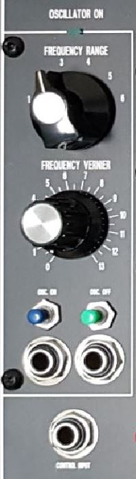
| The oscillator control section resides on the left side of the sequencer. The term "OSCILLATOR" is misleading though, as the T960 does not work with a CV driven oscillator internally, but under microcontroller control. The behavior for the user is similar though.
So the oscillator control section contains an osc status LED (the small rectangle below the "OSCILLATOR ON" engravement), the FREQUENCY RANGE selector determing the sequencer speed range, The FREQUENCY VERNIER pot for speed fine adjustment, an OSC. ON trigger to toggle between the run states of the T960, a corresponding input jack to do this with a pulse and the same for switching off the oscillator, which means for the T960 setting the sequencer in RUN STATE 0, like beeing just switched on. The sequencer run speed can also be determined by the CV input jack "CONTROL INPUT". In contrast to the original, which just activates the sequencer when the "OSC. ON" is triggered, multiple pressing of the trigger toggles thru the run states. That means after resetting the T960 or triggering the "OSC. OFF" function, the T960 is set in the RUN STATE 0. In this state the step trigger are processed, as the SHIFT trigger and SHIFT pulse connector on the right. Triggering the "OSC. ON" again sets the T960 in RUN STATE 1, which is basically the same behavior like the orignal, despite of the T960 extra functions. Triggering the "OSC. ON" again activates RUN STATE 2, 3, etc. Here an overview about the currently implemented RUN STATES and their functons: | 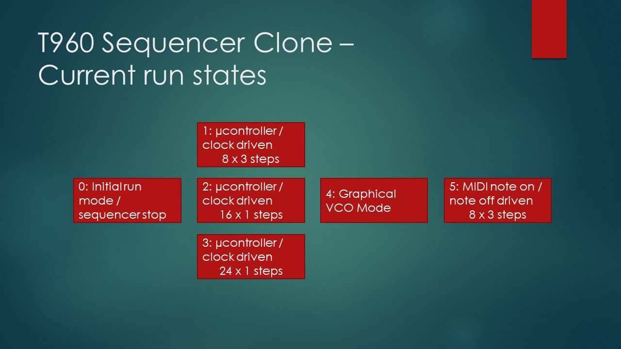
|
This is done, like the original does, with the step operation row:
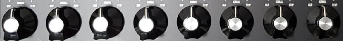
Each sequencer column is provided with a step control ("SKIP", "NORMAL", "STOP"). But as this is a column function, it is currently not adapting to the run states, at least with the current T960 OS version.
For RUN STATE 1 the step control works like it does in the 960. That means a step can be skipped, it can be performed normally or the sequencer stops ( = entering RUN STATE 0) if the corresponding step is reached. For the other run states "SKIP" means that each step of the sequence belonging to the corresponding column es skipped, and the first occurrence of a "STOP" stops the T960 immediately. Future software changes might handle this different.
Remark: The terms "step" and "column" have to be distinguished. The T960 provides (like the 960) a matrix of 3 rows and 8 columns. But this leads to a sum of 24 steps for the T960, but only 8 steps for the 960, due to a different row selection handling.

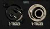
The step trigger row provides the "SET" trigger and the column "TRIGGER" outputs, where one or more trigger pulses are provided when a sequencer column is processed, dependent on the "RATCHET" selection (see below). The over all column independent trigger out (clock out, osc. out) is provided (in contrast to the 960) in two ways: as V-TRIGGER for driving non Moog synthesizers, and as S-TRIGGER for Moog synthesizers and components / modules, like the 911 ADSR:
Pressing a SET trigger selects the corresponding column. Then the voltages of the rows can be adjusted. The SET trigger are processed only in RUN STATE 0.
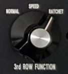
| The original 960 provides a switch here to decide to process the 3rd row in "NORMAL" mode or to use it for time control ("SPEED") of the current step. The T960 offers a third option: Activating the ratchet function ("RATCHET"). Ratcheting means that the trigger out per step is repeated up to 6 times depending on the 3rd row voltage of the current step, which leads to a note repetition of the synthesizer.
I provided a RUN MODE switch instead. "ONCE" means that the T960 is set into RUN STATE 0 after processing a sequence, which are 8, 16, 24 steps, or 8 MIDI steps dependent on the RUN STATE selected before. "ENDLESS" just lets the sequencer run. | 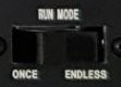
|
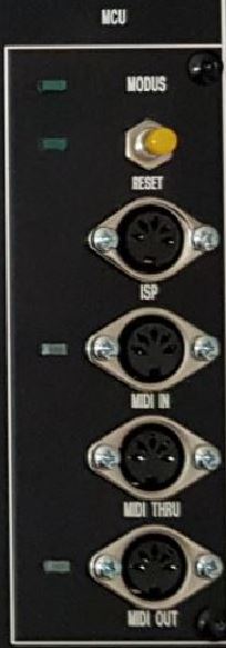
| The mostly visible difference between the T960 and the original surely is the MCU cheek to the right. It contains a MODUS LED to display additional status information, a RESET trigger for resetting the microcontroller and the sequencer, the ISP interface for uploading software and the MIDI DIN connectors of course. MIDI IN and OUT also display active data communication via corresponding LEDs.
MIDI: All microcontroller based modules of the Analogmonster synthesizer projects provide MIDI capabilities, and of course this sequencer also. I consider this as standard function, easy to implement on hardware and software side. For the T960 two forms of MIDI processing is implemented basically. First of all a MIDI on off sequence is created from the sampled voltages of the 3rd row. These volages are already used for the step processing speed in the original, so why not use it for controlling other synthesizers via MIDI? Additionally the T960 can be synchronized to an incoming MIDI sequence. This is activated by selecting RUN STATE 5. In the current version of the T960 OS each incomming NOTE ON NOTE OFF sequence lets the T960 process the next step. All oscillator control functions are disabled then, and the T960 follows the MIDI stream. |
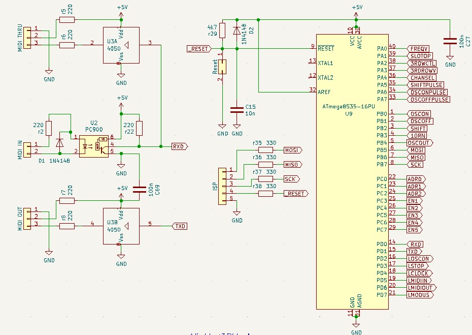
MCU and MIDI circuit
Again I used my current favorite microcontroller, the ATmega8535 with easy to handle 8Mhz. The Reset, ISP, and MIDI handling is standard, nothing special. But the circuit diagram shows the main architecture of the T960: Most functions are created by software. The PAn block does the AD conversion of several analogue voltages which carry the corresponding selections of the front panel or external pulse inputs for further processing.
Remark: A lot of information is transported analog within the T960. Functional selections on the front panel are translated in analogue voltages, converted by the MCU and interpreted from the software. See below selector examples.
For MIDI IN I used the PC900 opto coupler because I had it in stock, but any other type will do also.
The PBn block does some digital I/O like pressed trigger, ISP and trigger output.
The PCn block provides the column and the row addressing.
And last but not least the PDn block provides the MIDI I/O and enlightens us with several function LEDs.
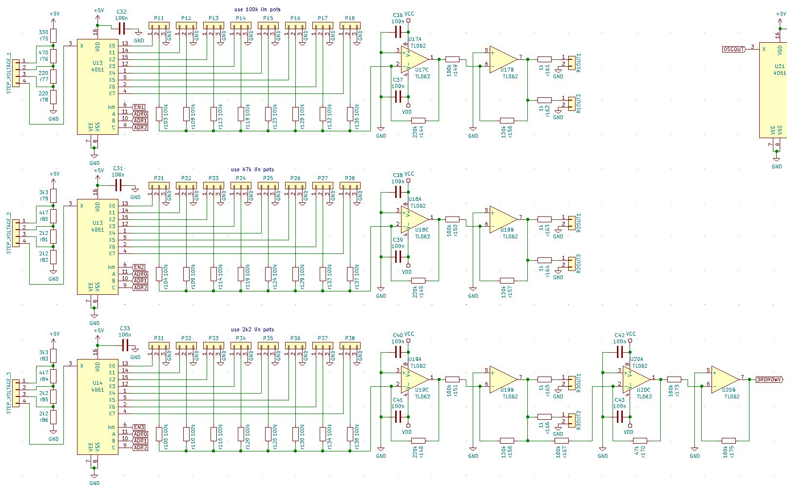
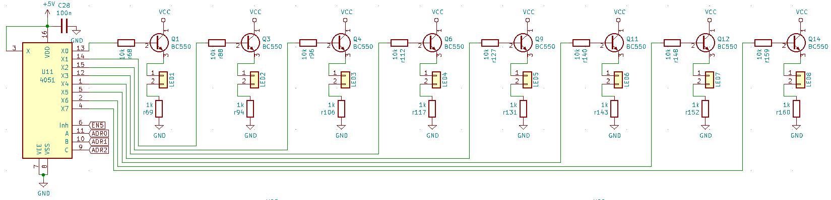
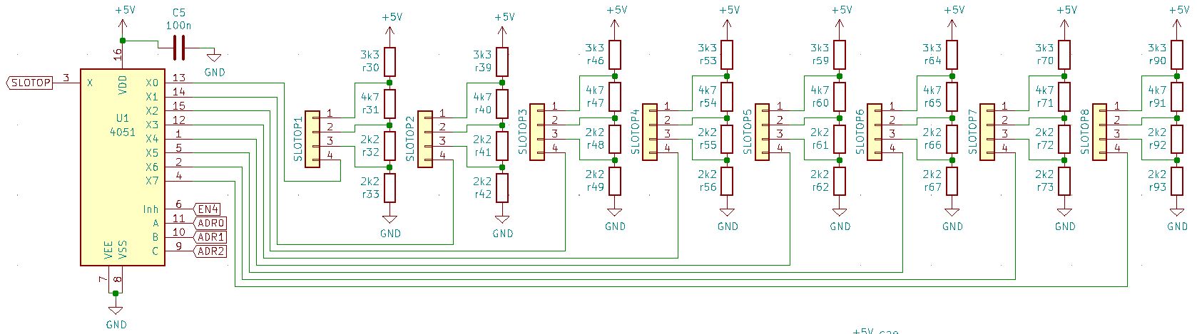
Potentiometer rows circuit
Here is shown how the sequencer row and column addressing works: The step voltage selectors select a voltage of the resistor divider chain behind. The 4051 demultiplexers are activated by the EN outputs of the microcontroller. That is the row addressing. The column is set by the microcontroller via the addr bits. A selected column output of the demultiplexer provides the voltage of the voltage selector at the corresponding step pot. The step pots work as voltage dividers, and their output is amplified by the output buffers to fit the 2V, 4V and 8V range. In case of the 3rd row 'C' another buffer stage leads back the step voltages to the microcontroller for further processing like MIDI out, step speed or ratcheting.
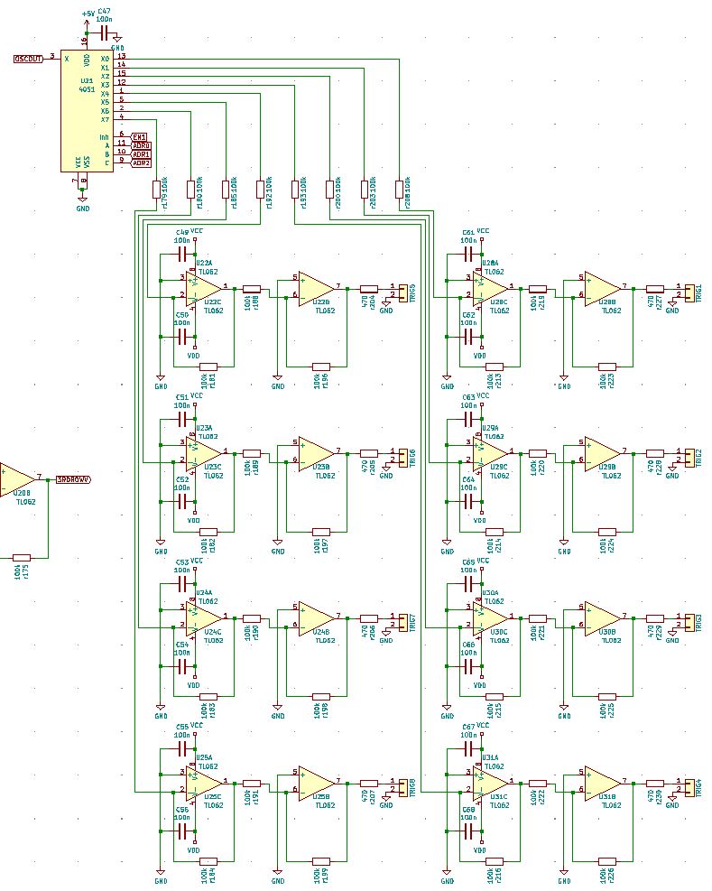
Trigger outputs circuit
The trigger output demultiplexer just spreads the clock output of the microcontroller to buffered trigger out connectors, depending on the column addressing.
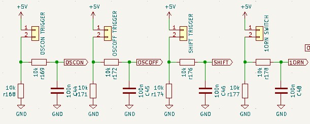
Frequency control circuit
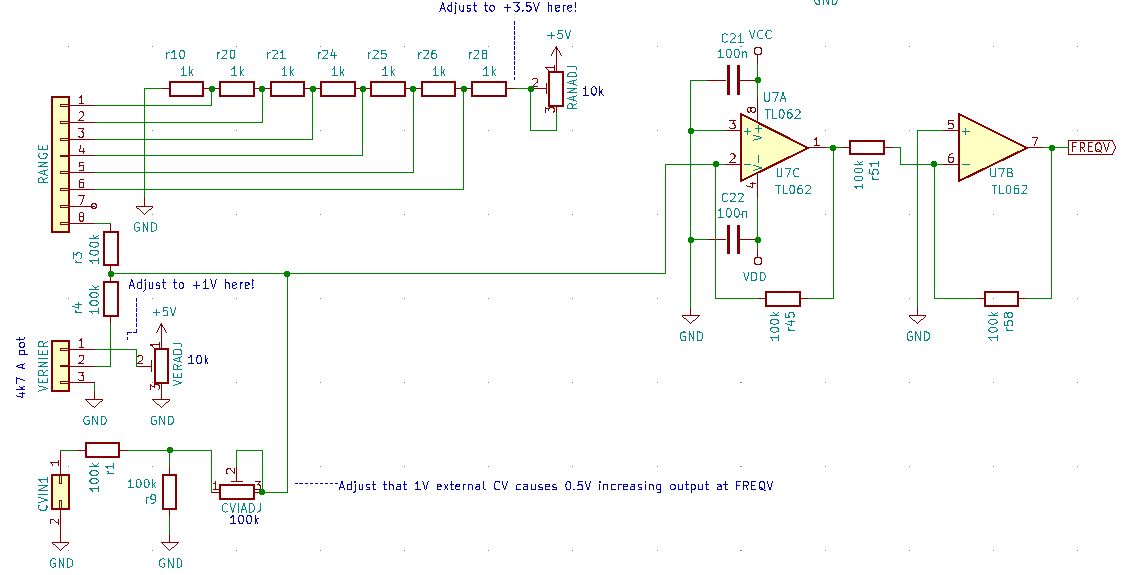
This is just simple control voltage provisioning for the microcontroller. The frequency CV is a mixture of a voltage divider chain, provided by the RANGE selector, a VERNIER pot with a voltage for fine adjustment and a CV input connector ("CONTROL INPUT"). VERNIER and CONTROL INPUT voltage adds can be adjusted to the desired amount of change. The voltage sum is converted and processed by the microcontroller to set the sequencer speed by software.
Column selection
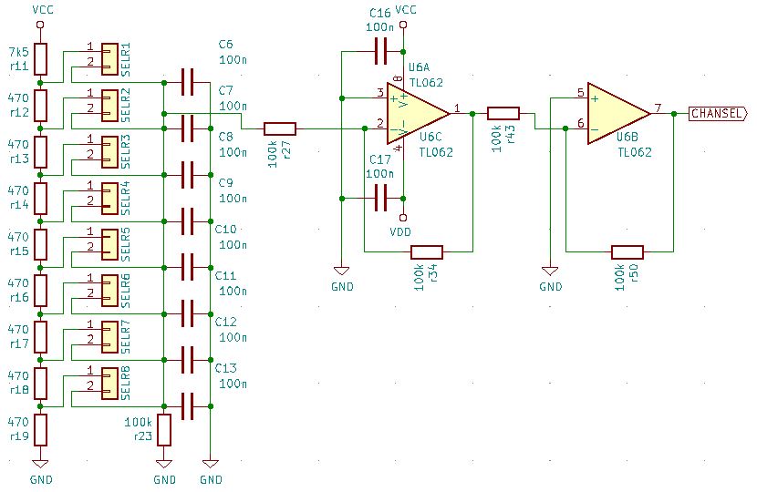
The same here. Each trigger selects an individual voltage from the voltage divider chain behind. The selected voltage is buffered and interpreted from the T960 OS as column selection.
Input pulses
Incoming pulses are buffered and interpreted from the T960 OS. Please note: These pulses are connected to ADC pins of the microcontroller. The interpretation as digital event is done by he T960 OS. Software changes can enable the T960 to process analog signals here also.
Functional LEDs
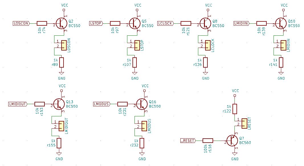
The T960 OS shows status or functional information here. The corresponding microcontroller output pins are buffered by NPN transistor stages. Only the inverted /RESET information is buffered by a PNP stage.
Column / Step LEDs
If the LED column row is activated via EN5, each column address selects a corresponding buffered LED stage via demultiplexer.
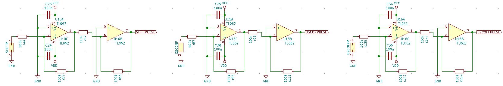
Functional Trigger
The functional trigger are debounced by the 100n capacitors and interpreted as digital event by the T960 OS.
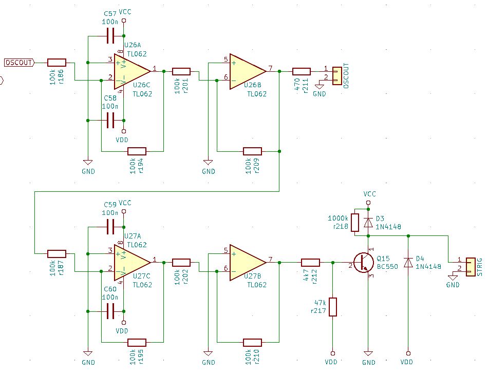
Clock / Trigger out (V/S)
The oscillator / trigger output is created by the T960 OS and buffered by a TL062 stage. Additionally the voltage trigger is converted in a Moog-style S-TRIGGER via another TL062 buffer stage and an transistor based inverter / current sink.
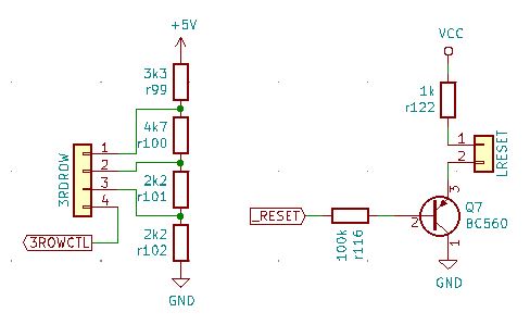
3rd row control and reset LED
The selection of the 3rd row function is also done by selecting a voltage from a voltage divider chain behind by a rotary switch. This voltage is interpreted by the T960 OS.
The /RESET LED shows the current /RESET status. It is dimmed in non RESET status end brighter if the reset trigger is pressed or reset is demanded by the ISP interface.
Column operation selectors
The selection of a column function is also done by rotary switches selecting analog voltages from the voltage divider chain behind. But in this case the demultiplexer is used in the other direction. A column address set by the MCU opens the channel of the corresponding rotary switch to the MCU, and the T960 OS can read the voltage and process the column as demanded.
Power supply
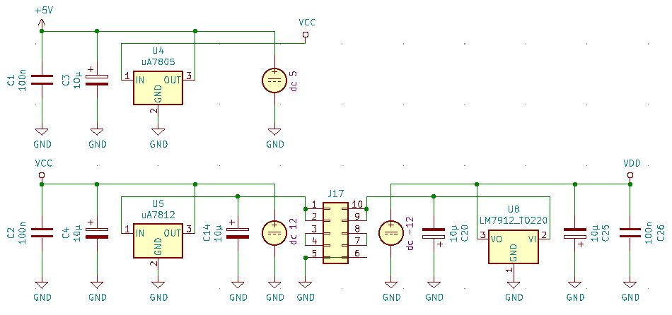
As done in all Analogmonster projects, the T960 is connected to the PSU bus of the modular system which provides +/-15V for the module. All needed operating voltages are derived from that by voltage regulators. The T960 needs +/-12V and +5V
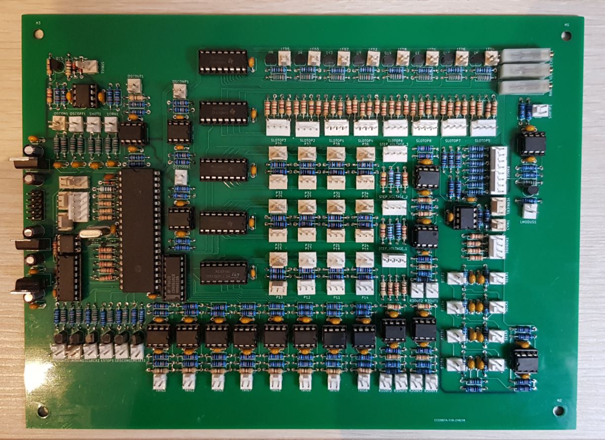
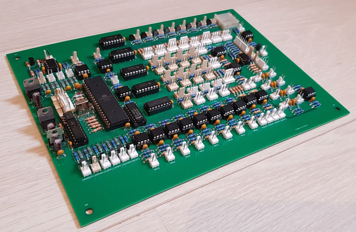
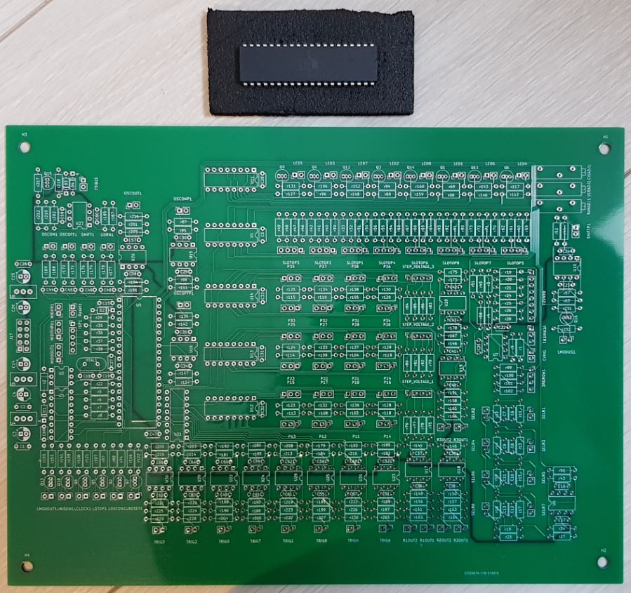
T960 hardware
| 
|
| 
|
Documentation
T960 OS V7YouTube
T960 Demo 1: Ratcheting and MIDI OutT960 Demo 2: 16 and 24 Step Mode
T960 Demo 3: Synchronization to incoming MIDI stream