So I was happy that Wavefront Semiconductor offered a set of ICs which promised a rather easy way to construct a digital effect module. This group of chips consists of the stereo ADC AL1101, the DSP AL3201B and the stereo DAC AL1201. Unfortunately all of them are available only in SMD packaging, so I had to solder SMDs with my stubby fingers the first time in my life (GRRRRR!).
By the way this set of chips is used in several Alesis devices like the Picoverb and others.
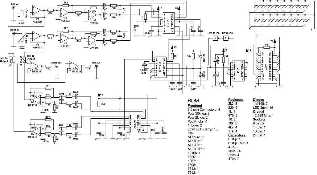
I designed this Module mainly by copying the circuit which is used by the DSP evaluation board provided by Wavefront Semiconductor. I just added a program switch (4520) and a corresponding display based on LEDs.
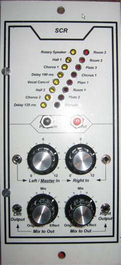
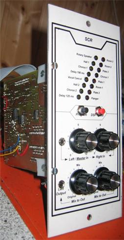
The module interface consists of a stereo input with level pots. The left input works additionally as a master input in case of using just one mono signal. It is overplugging the right input if that one is not in use.
The program trigger selects the effect programs. The selection is displayed with the LEDs.
The DSP can be reset with the DSP reset trigger.
The stereo output can be controled with MIX pots which mix the original signal with the effect output to be able to use an effect in a fat or smooth way. Very important for the different reverb functions of the module.
I have not added a programming or MIDI interface to this module version because I wanted to make experiences with the sound of the chip set and SMD handling first. But if I should build up more modules I certainly will do so.
The DSP is provided with 16 effect programs which can be used as they are without further parameterisation:
Delays: These are no pure delays or slapbacks but echo functions. The input signal is "fed back" within the DSP to create an echo.
There are two delay times selectable: 125 and 190 miliseconds. Besides the reverb effects these echo functions are the most important for me.
Chorus: These effects move and delay the input between the different outputs to get a kind od multivoice feeling. They differ in certain sound details which I can't specify. Please refer to the sound examples.
The reverb effects are quite dominant. These effects should be smootherized by the mix-to-out-pots, and then they sound very well. I built this module exactly for these reverbs.
Together with the plates you have a quite wide spectrum of reverb effects in this module.
Vocal Cancel: I have not tested this function yet. Although I would like to know how it works I think it is an absolute unnecessary feature.
Rotary Speaker: Seems to be a kind of leslie, but as I don't have one in real I can't say much about it. With a triangle input it sounds a bit like an accordion.
Flanger: Difficult to describe. A bit like phaser. Please check the sound examples.
Room effects: They make an input signal sound like beeing played in rooms with different physical attributes.
SCR board (top view)
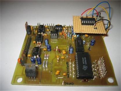
Top right: The forgotten Schmitt-Trigger :-( and the output stage.
Bottom right: Display demultiplexer and program selection counter.
Left side: Input stage and signal processor.
As already mentioned the circuit approximates the DSP evaluation board circuit and works as follows:
Both input signals are transfered to the ADC in an inverted and non inverted form (In Left, /In Left, In Right and /In Right).The ADC sends the digitalized data to the DSP in 32 bit portions. The DSP synchronizes the ADC and DAC with his word clock signal. The DSP computes the output data according to the selected program and sends them to the DAC which generates the output analog signal, inverted and not inverted. This output signal is summed in another opamp stage and is provided by the output opamp stage.
The method of program selecting is just incrementing a 4 bit counter by a trigger. As the provided program(number)s fit to a rotary switch encoder (whatever that is), the sequence of effects seems to be a little bit strange if selected by a binary selection. Anyway, this has no meaning for the module functions.
Unfortunately I forgot the Schmitt Trigger in my first program-selection circuit version and therefore also in my PCB (please refer to the circuit diagram). The result were non deterministic jumps in the program selection while pressing the trigger. Thats why I installed the piggyback board carrying the 40106.
SCR board (bottom view)
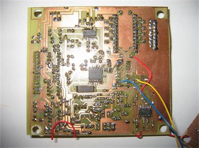
Soldering of the SMD components was not as difficult as I thought at the beginning of the module development. I did not kill the ICs with static electricity and I did not kill them by heat due to long time soldering. These were the things I was afraid of.
I fixed the SMDs on the board by using very small snippets of double faced adhesive tape and then baked the pins to the copper. Oh I was so happy when I realised that the chips were still alive (sigh).
Schematic:
Schematic
Sound examples:
The module sounds very well. I was surprised about the quality of such a simple module, and there is very low noise. But some Effects should be used carefully. I think that an echo can be more dominant than a reverb. The following examples consist of the original and the effect signal to compare them:
Reproduction hints:
As already mentioned the soldering of the SMD components was no problem because the SMD packaging of the Wavefront chip set contains pins in rather wide distance from each other. I used a Weller 15W soldering iron to solder the pins after fixing the IC with double faced adhesive tape. The rest of the construction was also no problem. I provided two ground areas (AGND and DGND) which are connected just in one single point. The output signal does not contain any noise or spikes, but I don't know whether there would be any interferences using just one single ground area.