Assembly report and circuit description
Well, there is nothing special or tricky in the circuit. As I don't have much electronic know how I am glad that everything seems to work fine. I collected most of the circuit parts from other web pages; if somebody recognizes a part as 'his' or 'her' development, I will thank him or her and hope that he or she is generous enough to allow me to use / show this part in my circuit or documentation, if not, please let me know. I will remove it from the documentation.Important notice: clicking on the schems means ACCEPTING THE DISCLAIMER on bottom of the page!
Control unit
I started with the ISP interface of course to be able to test all new functions without removing the controller. I continued with the display interface to be able to display status or debugging infos of new functions. The display interface works with the standard HD44780 lcd displays incl. backlight function. I don't use backlight with my actual display (the backlight lcd module in 4x20 was too expensive, but I testet with a 2x16 backlight display).Next thing was to connect and test the function keys. Everything worked fine. Then I built the DAC. I use the DAC08, but only in a 6 bit resolution. Later on I recognized that I was fixed in my 5 Octave environment with one semitone / bit using this resolution, but this seemed to be ok for me for using the UCVM as a MIDI2CV. And I did not want to do a redesign. Additional to mention that I had my quantizer implicitly :-)
As I did not want to use too many wire bridges I connected the port pins of the controller to the input pins of the dac as easyly as possible, so thats why I do a bit conversion in the coding.
After that I testet the Analog In channels and I wrote a little routine just for fun to read the Analog 1 input and put the result on the dac, and I had my quantizer, yeah! I testet it with my formant VCOs and realized that my old formant keyboard has a problem in its upper half (CV jump), which I had compensated with VCO adjusting, so now I have to do a new VCO adjusting, hmpf!
Last thing of the control board was to build and test the MIDI connections. That was quite difficult and very frustrating for me, because I got in contact with the MIDI protocol the first time in my life. I wrote the software for the MIDIMON to see the incoming MIDI messages and plugged in my old ELKA EK22 synthesizer. This veteran, glad to be reactivated, startet with an orgasm of $FE bytes which I saw on my MIDIMON display ('...what the hell is this filling my display making no sense...'). First I considered it as an error in the MIDI IN current loop interface or in my software, but then I realized (via oscilloscope) that it came directly from the ELKA meaning 'Active Sensing' (according to my MIDI documentation). Yeah, great, this was very 'active', but sensing? What does this sensing expect as an answer? Another synthesizer yelling 'Hi', or a slap into the face from a 'sensed' woman? Well, I immediately killed this nonsense in my MIDI In routine and then I saw something that looked like a MIDI message, three bytes starting with a $90, but followed by trash. I made some experiments, but nothing helped. Key pressed, three bytes, key released, three bytes, but no sense behind the $90. But then I thought: Receiving MIDI does not send an acknoledge, so sending MIDI sends three bytes or more in one stream, and my software just was too slow to read a byte, convert it into hex and display it in the MIDIMON and then to read the next MIDI byte. I programmed a stack solution, and everything worked fine.
GATE and CV unit
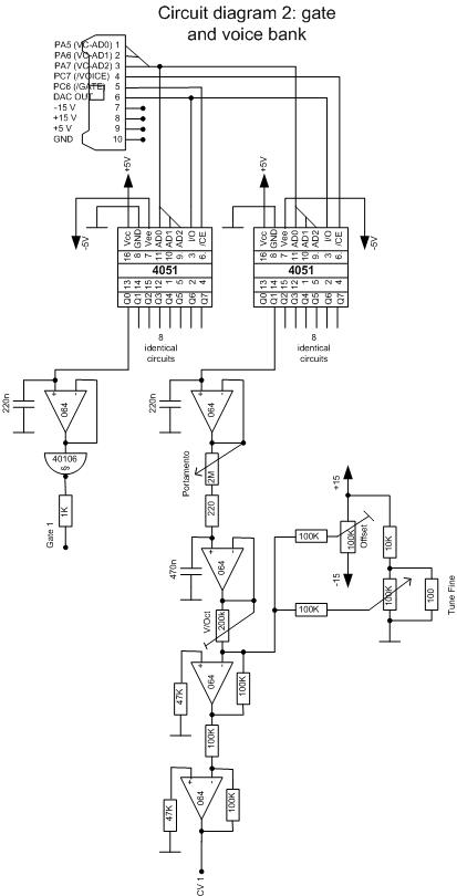
Both the GATE and the CV bank work with analog storage of the voltage provided by the DAC, so I built just one DAC and multiplexed it with two 4051.The first 4051 transmits the voice depending GATE voltage (0 or 5V) to a capacitor, which is followed by a voltage follower (1/4 of a TL064) and an inverting Schmitt Trigger (1/6 of a 40106). Because the Schmitt Trigger is inverting, the software generates 0V to activate a GATE and 5V to deactivate it.
The second 4051 transfers the voice depending note voltage to a capacitor, which is also followed by a voltage follower (1/4 of a TL064) and a simple portamento circuit consisting of a portamento pot and another capacitor. The portamento stage is followed by (yes, you are right!) another voltage follower and a voltage adder stage to do the +/-0 adjustment and the semitone fine tuning. This stage is followed by (incredible!) a voltage follower acting as the output.
The 200k trimpot between stage 2 and 3 works as a V/Oct adjustment. This was necessary to compensate component tolerances.
Schematics and software Please see the disclaimer on page bottom!
Experiences I made working with the module
Well, if I had to design again another module like that or a similar module I would do some changes in different parts. But this is the purpose of an experimental module, to learn how to realize functions or how to make them better or easier.First of all: All functions work satisfying, but to achieve this I had to compensate some hardware design failings by additional software functions, so some hardware design changes would make software development faster.
One thing which can't be compensated by software is the 6 bit resolution of the DAC. This is the minimal resolution to fulfil 5 octave requirements and that works fine, but that means you can't use the dac for other purposes (fine tuning for example). I did this to save connections between µC and DAC, but now I would use 8 or better 10 bit resolution to have a scalable quantizer and to be more flexible.
Next thing is that the ADC functions of the µC could work better. Constant voltages differ +/- 0x020 in their ADC results from measurement to measurement. I think this is the result of saving a precise reference voltage and reference ground circuitry (instead I connected reference voltage to 5V supply and reference ground to ground).
Last thing is the fact that I used the pins for RXD and TXD also for the display bus which results in the need of higher discipline in programming MIDI I/O and display functions (I had some bad collisions, he he).
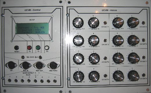
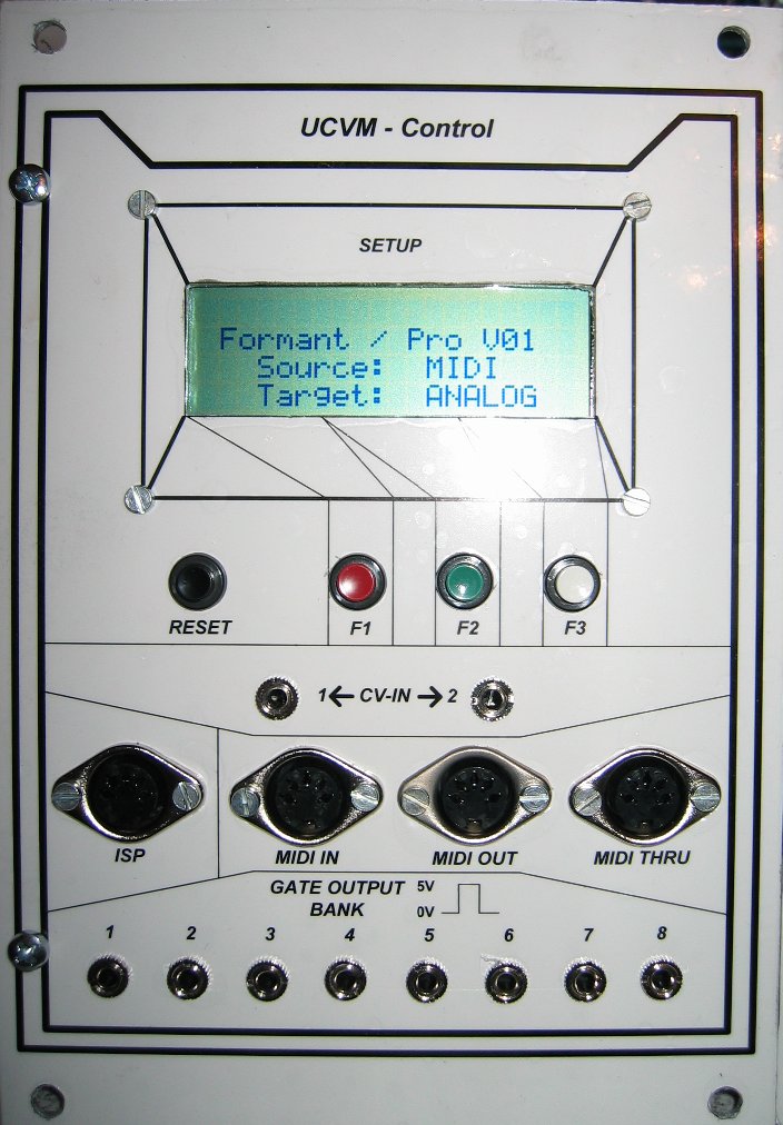
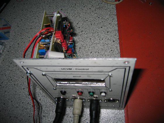
First unit of the UCVM: The control module with 4x20 character display, reset and function keys, the two analog inputs, ISP interface, MIDI IN OUT THRU and the eight GATE outputs.
 Click to enlarge
 Click to enlarge
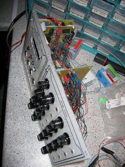
Second unit of the UCVM: The voice module with eight analog outputs. Each analog output has a fine tune and portamento knob (No, I did not want to program fine tune and portamento, and the DAC in the module has only 6 bit resolution for 5 octave tone values, so I implemented an analog solution for fine tune and portamento).
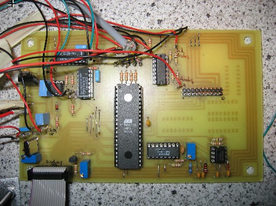
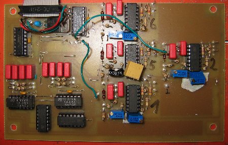
Control board with µcontroller, ISP and MIDI interface, function keys, analog input, display interface and DAC.
GATE board with GATE bank and four of the eight CV output stages.
Voice board with the rest of the analog outputs.

PCB - Printed Circuit Burger
PCBurger and Pasta
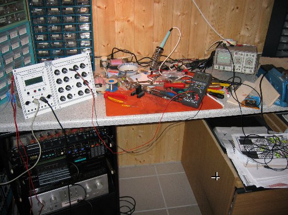
Final module test at the workbench...