Intro:
Now this is the third keyboard controller I've developed so far. Compared to the two controllers I built for the Formant this µNet version has some additional features I 've had on my wishlist for a longer time, e. g. higher performance and a joystick.
Additionally some new features had to be added to fulfil the requirements of the µNet concept like the ability of saving all adjustments in EEPROM / ability to reproduce these adjustments and the ability of receiving and executing commands of the µNet MCU.
Features:
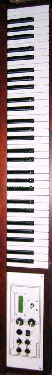
Panel of the keyboard controller:
As one can see I am not the master of the metal rasp
Mode of operation:
| The circuit is built around an Atmel AT90S8535 µcontroller which scans the keyboard in 8 bit words meaning 8 neighbour keys at a time. As each key has two output contacts which close with a certain time difference it is possible to detect the velocity the key is pressed with. This information is added to the output MIDI sequence as the loudness byte. This is done by the µcontroller, and this information is weighted by the KVS adjustment (Key Velocity Sensitivity).
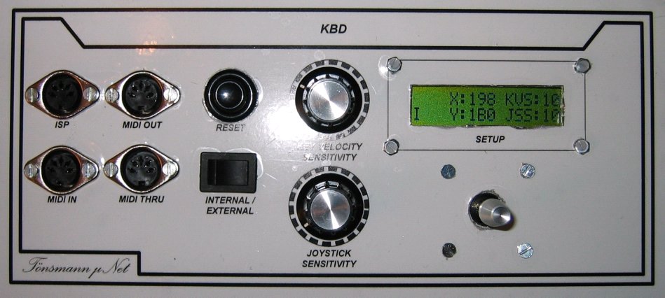
Another input control is provided by an analogue joystick which is scanned by two 10 bit A/D - channels (one per axis) of the AT90S8535. This results in a resolution of 1024 positions which are displayed in hex (000 - 3FF) on the LCD. Well, this is of course the max resolution and not really reproducable, so the sensitivity of the joystick can be adjusted by the JSS encoder (JoyStickSensitivity) in 16 stages. The joystick movement is translated by this software version into MIDI controller change sequences regarding the X-axis and into pitchend sequences for the Y-axis. The joystick position (X and Y axis) are displayed on a two 16 character row LCD in hex values as well as the values for KVS and JSS. If the Internal / External switch is on external position the display works as a simple MIDI monitor (or better to say a monitor for 'serial activity') as shown on the right. Here two keys of the Formant were pressed and released in sequence. Additionally all external MIDI (serial) signals are transferred to the µNet MCU internally and the built in keyboard is switched off (well in fact this part has still to be programmed). | 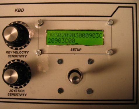 |
To fulfil the requiements of the µNet concept I don't use pots any more, because poti positions can't be stored in EEPROM memory and reproduced easily. So I changed to rotary encoders to keep the look and feel and usability of pots. As the detection of the movement direction of an encoder has to be done by analysis of the phase difference of two square signals provided by the internal encoder contacts the scan of an encoder is not too easy, but it was possible to do it by controller software quite easily. And one important point: One can determine the amount of impact of the rotary movement much more sensitiv than with real potis, addtional to the ability of storage and reproduction!
Board of keyboard controller: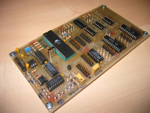
| As one can see easily this is a prototype.The huge amount of pin rows serve as experimental connections from the different circuit parts to the data bus of the µController.
In the front part one can see the MIDI inputs, thrus and outputs, opto isolators and controls. The fat mommy in the middle is the AT90S8535 of course. Below that one can see the 'display terminal' and the bus transceiver for the connection of the keyboard. The circuit above should interface the swtch, encoders and the joystick and was replaced by controller software and therefore obsolete, that's why there are some empty sockets. So not much hardware at all. |
| Built in and working means some more action on the board, as one can see. | Board in action: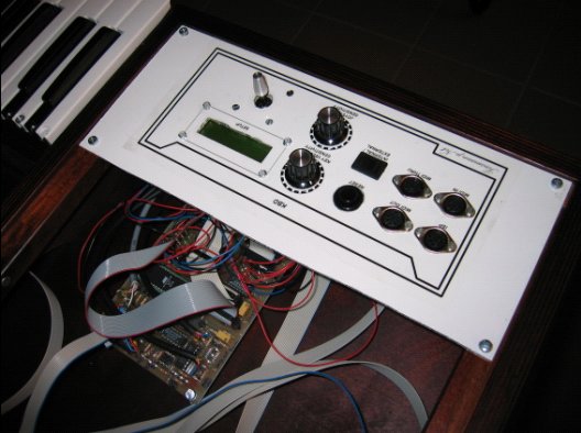
|
Reproduction hints:
None.
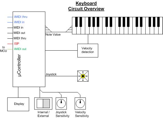
Block:
Block diagram
Keyboard Contacts:
Fatar Interface
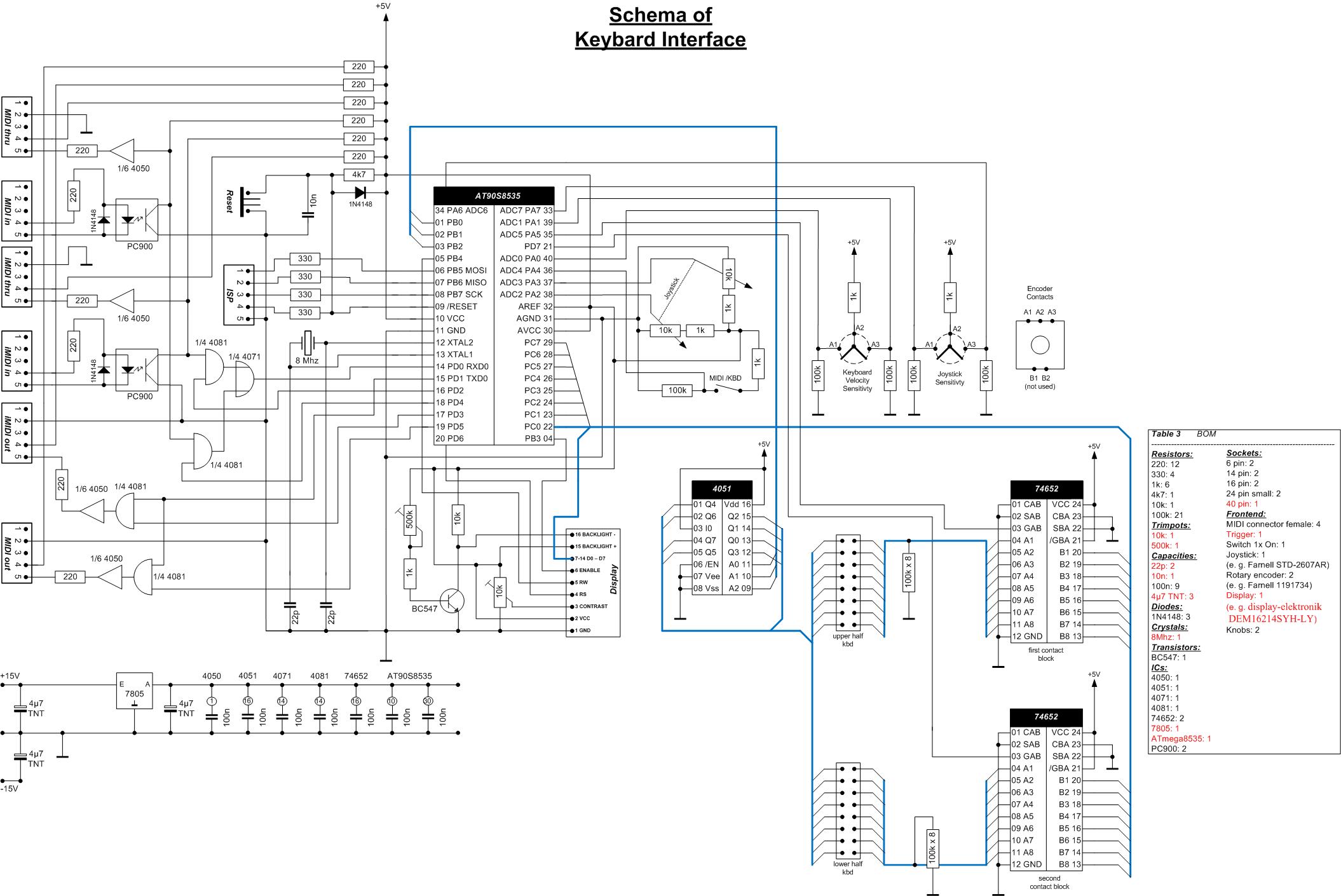
Schema:
Clicking the schema means acceptance of the link disclaimer of page bottom!
Source code:
Clicking the source code means acceptance of the link disclaimer of page bottom!