Additionally the filtered frequencies can be amplified in a resonance loop.
These filter parameters can be controlled:
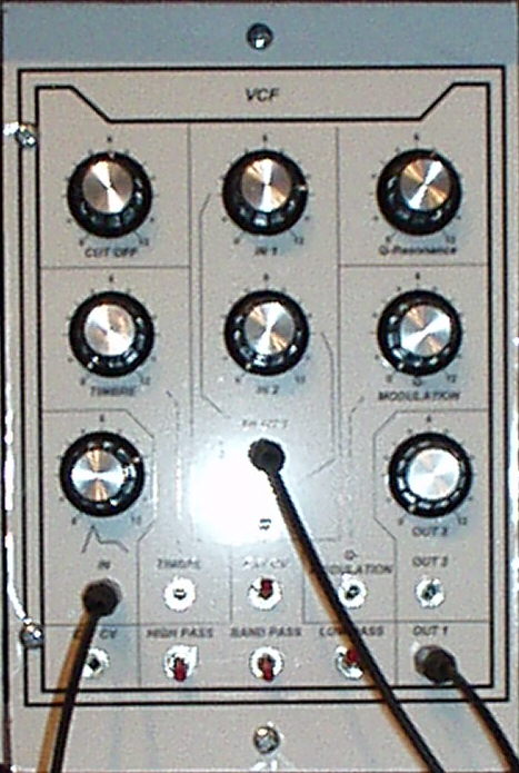
- CUT OFF: Maximum filter level. Level 0 means possibility of filter depth until sinus level, 12 means no filter influence on the sound at all.
- Q-Resonance: Maximum resonance amplification level. This parameter also can be controlled via control voltage(Q-Modulation).
- TIMBRE: Control voltage input for dynamical change of cut-off-frequency (e.g. by LFO).
- ENV: Control voltage input for dynamical change of cut-off-frequency (e.g. by ADSR).
- HIGH PASS: Switch to activate the high pass function of the filter. This function allows all those parts of the input signal frequency spectrum to pass the filter which are higher than the cut-off-frequency the VCF is currently working with.
- BAND PASS: Switch to activate the band pass function of the filter. This function allows all those parts of the input signal frequency spectrum to pass the filter which are close to the cut-off-frequency the VCF is currently working with.
- LOW PASS: Switch to activate the low pass function of the filter. This function allows all those parts of the input signal frequency spectrum to pass the filter which are lower than the cut-off-frequency the VCF is currently working with.
These main filter functions can be run in parallel mode. If you activate the low and high pass function the resutlt is a notch function.
- The level of both input signals can be adjusted; output 2 also.
Schematic:
The schema is part of the book "Formant Pro MSS 2000" by H.J. Helmstedt.
Sound example:
VCF controlled by an ADSR.
Reproduction hints:
None.