Introduction:
This module is a universal, but essential helper module for any modular synthesizer. You can mix DC and AC content which makes it to a universal mixer for likewise mixing of control voltages and audio signals.
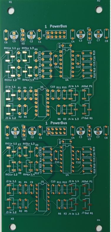
For maximum outbid of the frontpanel space, I built two circuits of it on one PCB. So the user gets two cascadable four channel mono mixer stages in one module.
The AC/DC Mixer:
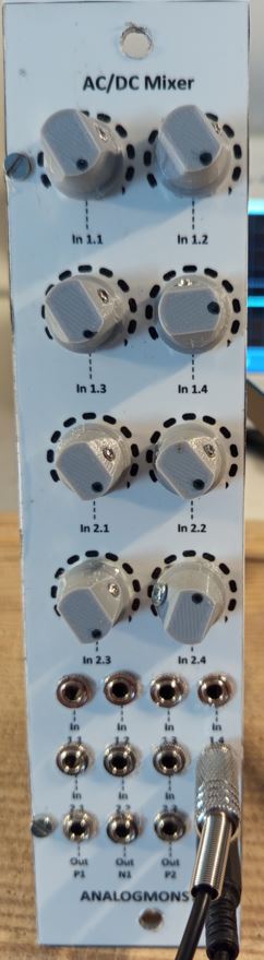
As I noticed that I hate cable pasta in front of pots, I separated pots and jack bushes from each other. The upper four pots attenuate the input row "In 1.1" to "In 1.4", the lower four pots the input row "In 2.1" to "In 2.4". The resulting mixture is provided 1:1 and inverted at the corresponding output jack bushes "Out P1" (1:1), "Out N1" (inverted) and for the second mixer at "Out P2" und "Out N2".
If you connect one output of one mixer to an input of the other mixer, the stages are cascaded.
Schematics:
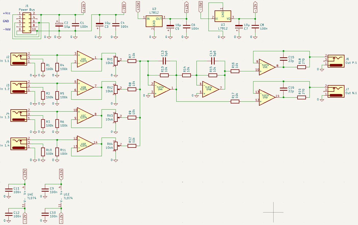
The schema shows one mixer as an example.
The supply voltages +/-12V are derived from the cabinet's power bus (J1, C2, C1, C3, C4, U2, C5, C6, U3, C7, C8).
The signals of the input jacks (J2 - J5) are decoupled from the voltage followers (U1A - U1D). Both the signal and the init contacts of the input jacks are pulled to ground with 100k resistors to obtain a defined init situation even if the input is not used (R1, R4, R2, R5, R3, R6, R10, R11).
The decoupled input signals and voltages are mixed with the input attenuators RV1 - RV4 and the inverting mixer stage (R7, R8, R9, R12, U4A, R13, C13). U4A, R13 and C13 form an active first order low pass filter with fc = 2.8 Mhz for suppression of unwanted self oscillation.
This inverted mixture is provided at the output (J7) via another active low pass filter and output buffer (R17, U4D, C16, R19).
In parallel the inverted mixture is inverted again with the active inverting low pass filter (R14, C14, R15, U4B) and the active low pass filter and output buffer (R16, U4C, C15, R18) and is provided as 1:1 equivalent at (J6).
AC/DC Mixer Module
| 
|
Offer: PCB of the AC/DC Mixer for Euro 25.00 | 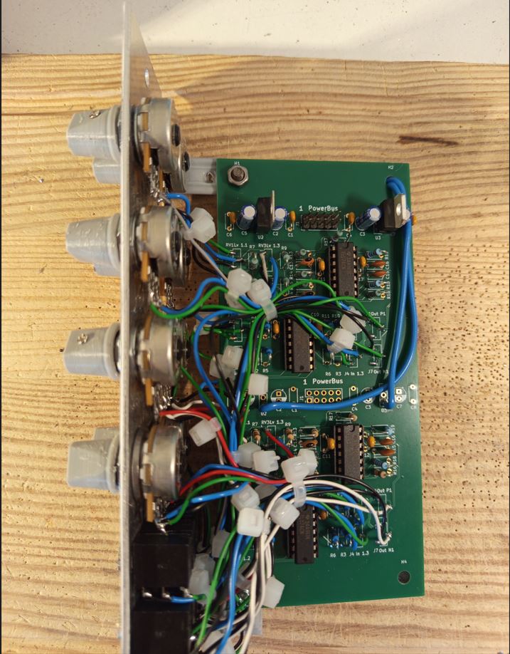
|