Introduction:
Chapter 2 and 3 of my Oberheim-SEM-Clone-2-SMD - activities handle the VCA- and ENV- sub function of the Oberheim SEM. At the beginning just a feasibility study, I integrated them into my third modular system now as combination module, or better to say as module with two functions, because I built it, so I use it...
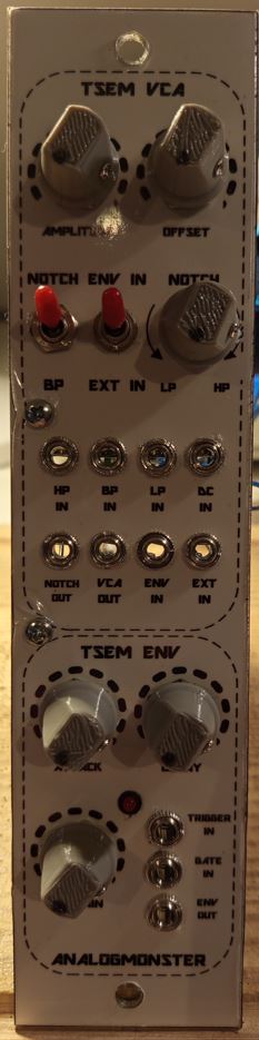
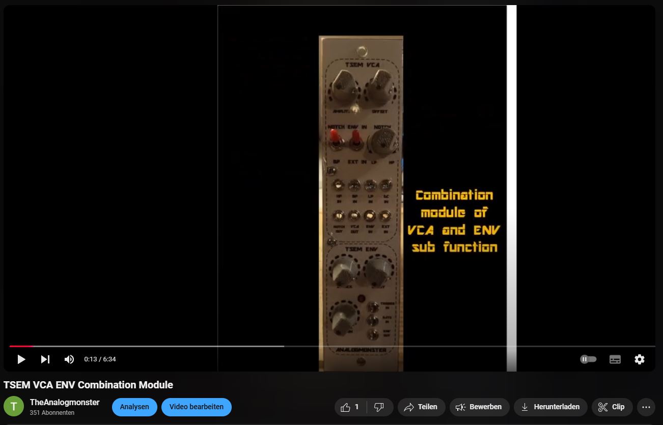
The TSEM VCA ENV:
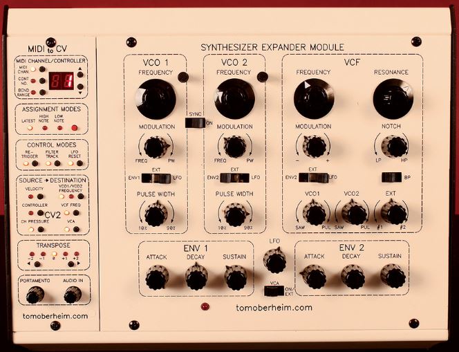
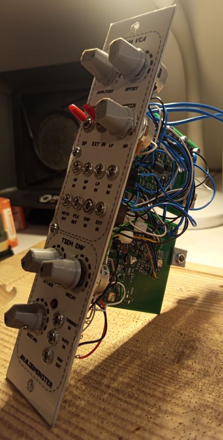
If you compare this clone with the original (see below), you see the additional control elements and connectors at the front panel immediately, which you can't find at the original. These are the outer equivalents of the internal connections and functions of the original SEM which are not needed as external elements there. The TSEM VCA ENV as stand-alone module must expose them obviously to be usable.
| The TSEM VCA ENV: | The original: | |
|
| ---------------------------- | 
|
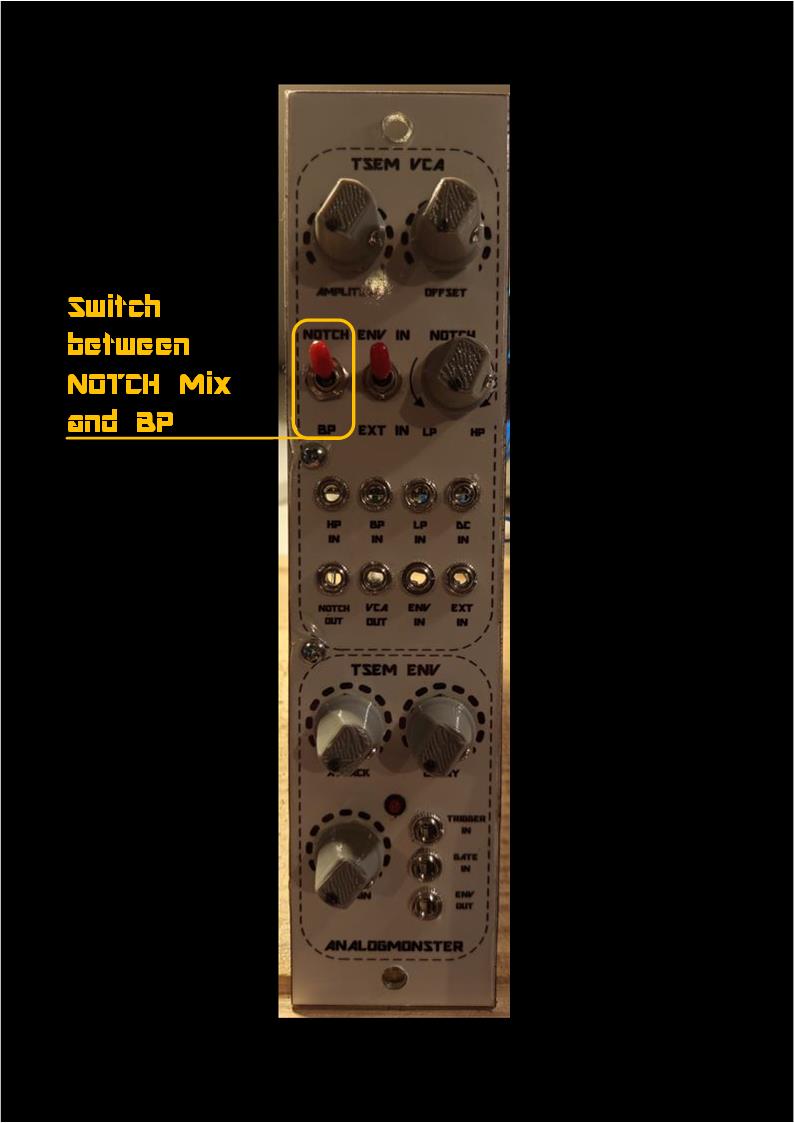
As you can see, the VCA is not indicated as visible element (as dotted oval) on an original SEM front panel like other sub functions (VCO, VCF, ENV). The VCA control elements are integrated in the areas of other sub functions. The LP-NOTCH-HP - morphing of the VCA has been added to the VCF control elements, like the NOTCH-BP changeover switch (whereat the "NOTCH" engravement has been omitted totally). The ENV-EXT - changeover switch for selection of the control voltage source is located between ENV 1 and ENV 2.
The ENV sub functions on the other hand are visible in the original indeed.
ENV:
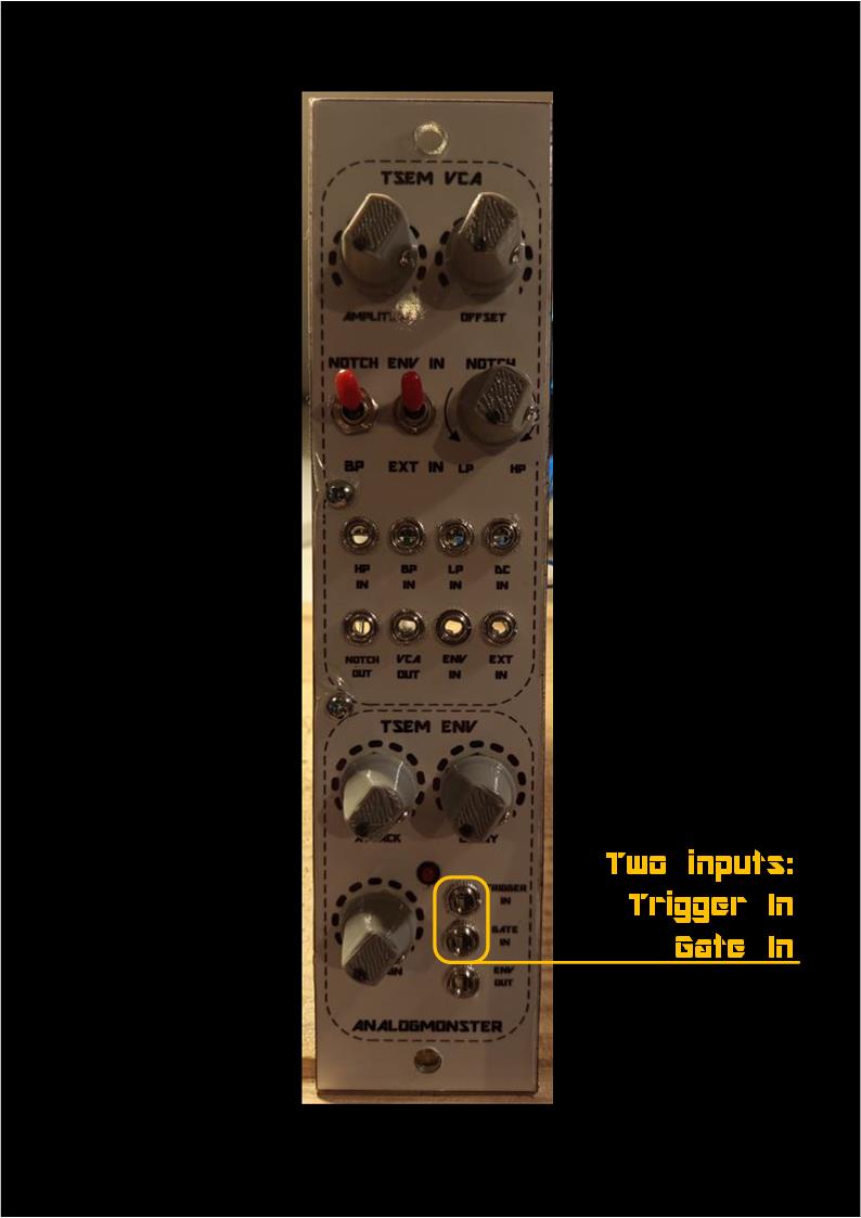
Looking at the original Oberheim circuit you see, that, to invoke an envelope creation, two parallel control inputs are used, a trigger input and a gate signal. This was new to me, especially under consideration of this weird timing and connection diagram of that circuit.
As I cloned the circuit close to the original, I obviously cloned that input duality as well and provided those inputs for my TSEM VCA ENV for further experiments. But I was not enlighted in any way though.
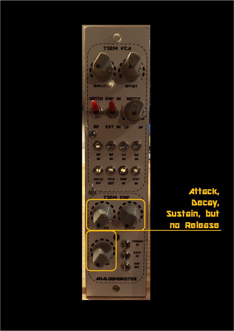
And this is not an ADSR module. There is no RELEASE adjustment at all, as long as you use it just as a stand-alone module. But I must admit that I am far away from understanding the module or the Oberheim engineers thoughts, especially as I don't have an original SEM device to compare with.
Might be, that the access to the original SEM ENV sub modules e. g. in an Oberheim 4-Voice via keyboard and programmer logics is performed in a different way compared to stand-alone and outer access. So there is much more research to invest to clarify that.
Anyway, the observed circuit behavior up to now is as follows: A gate or trigger signal at the TRIGGER IN connector launches an envelope creation. In this case an envelope timing is the sum of the ATTACK and DECAY timing.
The SUSTAIN setting is ignored totally though.
A gate signal at the GATE IN connector initiates an envelope as well, but this time ignoring the ATTACK timing value. The envelope rising and falling time both is dependent on the DECAY setting. But this time the SUSTAIN level becomes important. For instance if setting the ATTACK to 0 and DECAY to 0 the resulting envelope follows the GATE ON and GATE OFF with the voltage set up with the SUSTAIN pot.
As mentioned above I still don't know much about that circuit.
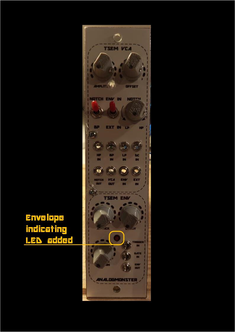
But I added an envelope indicating LED to it.
ENV Human Interface
| 
| 
|
VCA:
The VCA kernel of the Oberheim SEM sub function is standard (see circuit description below), but there are some special functions added to the VCA in total.
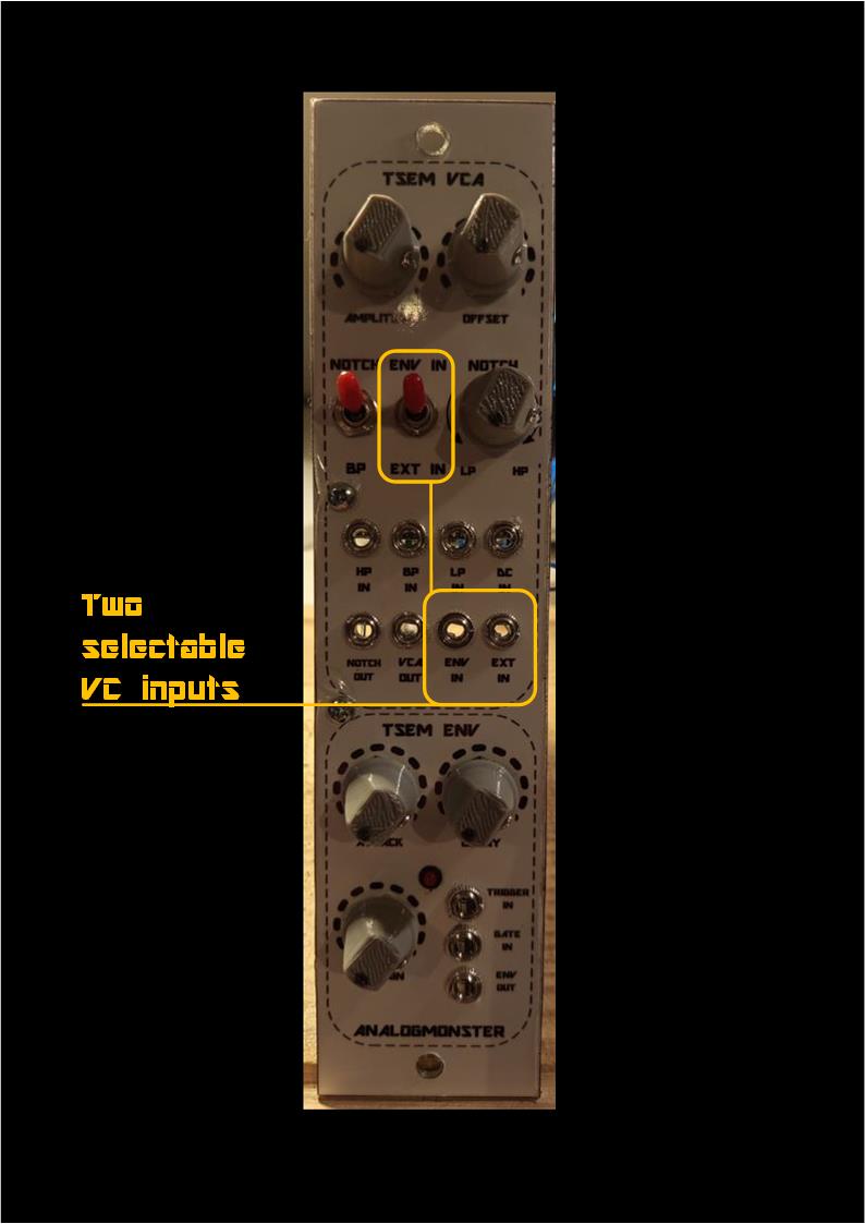
Like the original my VCA clone provides two switchable control voltage inputs, here labeled with ENV and EXT. Due to lack of an original device I don't know whether those have been used lets say in an Oberheim 4 Voice to interface the central programmer and the local SEM ENV 1.
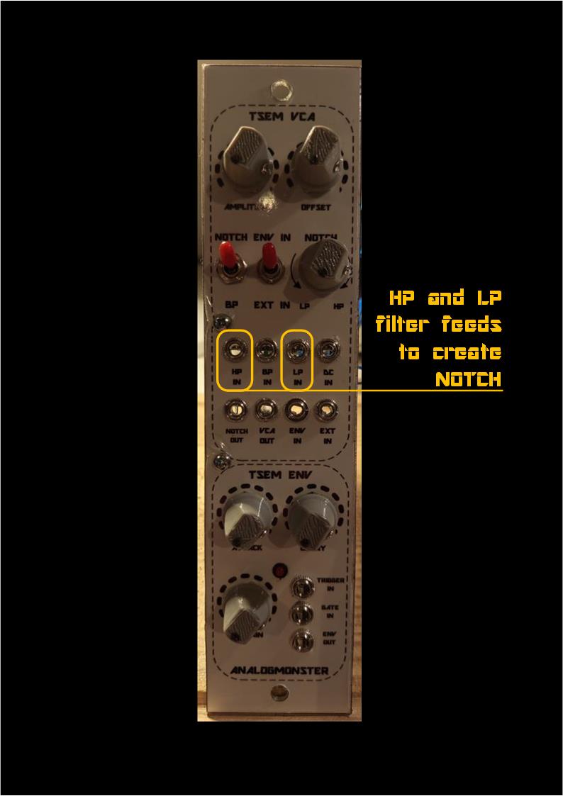
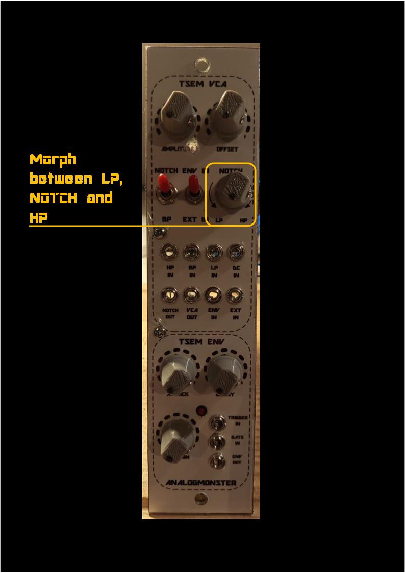
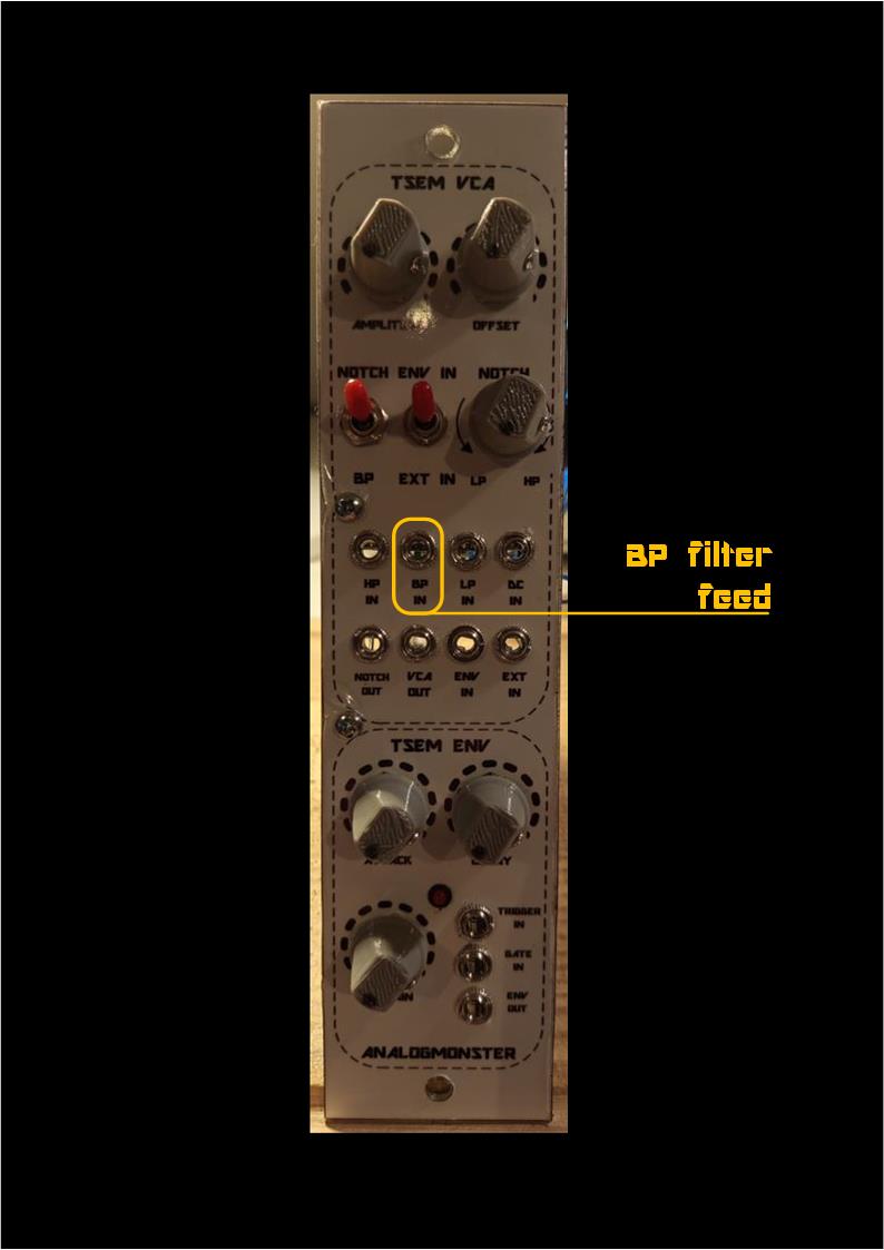
The additional task of the original SEM VCAs is the processing of direct VCF output feeds. Goal is to create the additional filter function "NOTCH" and the possibility of morphing between the low pass output of the filter, the NOTCH function and the high pass filter output and to switch to the contrary, the band pass output of the VCF. I don't know why the Oberheim engineers added these filter functions to the VCA circuit though, but anyway, my clone offers the same functionality. For that the TSEM VCA ENV module offers corresponding inputs for the LP, BP and HP filter outputs just as a morph pot for the filter morphing mentioned above and the switch from NOTCH to the band pass filter function.
Just to be sure I added two additional control features on the front panel: AMPLITUDE and OFFSET.
With AMPLITUDE you change the impact of the control voltage inputs on the VCA. This results in a kind of volume control.
With OFFSET setting you can minimize the control voltage bleed-thru.
VCA Human Interface
| 
| 
|
| 
|
Schematics:
The original circuit parts and elements which you can find in the net can be recognized easily.
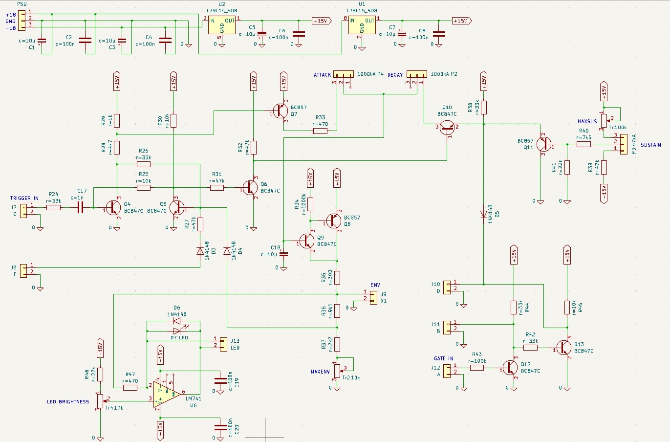
TRIGGER without GATE: An incoming TRIGGER pulse or TRIGGER signal (just the rising edge is important) sets the flip flop Q4-Q5 via R24 and C17. Q6 opens, Q10 closes and the elko C18 (capacitor load <=> envelope) is charged via ATTACK. The envelope voltage is buffered with Q8 and Q9, level shifted and provided at port X1 via R35. At the end of the ATTACK phase the flip flop is reset.
Now Q10 is opened again, and C18 discharges via DECAY. You can see in the circuit as well that the SUSTAIN branch is not used in this scenario.
GATE without TRIGGER: An incoming GATE signal is buffered and level shifted with Q12 and Q13. The emitter of Q10 goes high. As Q10 is open per default, C18 is charged via Q10 and DECAY in "wrong direction". After falling GATE signal C18 is discharged via the same components, but this time in the correct direction. This time the SUSTAIN branch is involved as well, as the SUSTAIN voltage is provided at the emitter of Q10 additionally.
Both GATE and TRIGGER are provided: ATTACK, DECAY and SUSTAIN all are used to create the envelope. The length of the DECAY phase is dependent on the SUSTAIN voltage though. Not adjustable here.
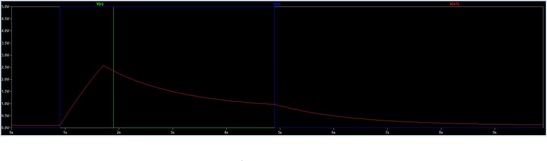
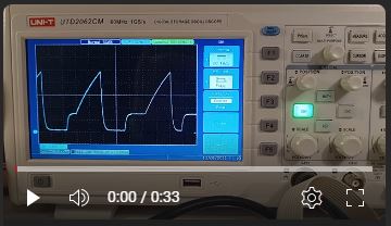
V(c) green: Trigger, V(a) blue: Gate, V(x1) red: Envelope
YouTube video of weird envelopes created by random TRIGGER and GATE inputs:
Gates and Triggers Demo
Looking closer at the circuit you see more manipulation options of the envelope creation process:
- [J8 E]: Reset of the flip flop independent from the envelope
- [J11 B]: Inverted GATE signal
- [J10 D]: Level shifted GATE signal (output)
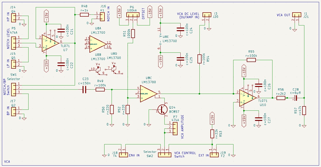
Again the original circuit parts and elements which you can find in the net can be recognized easily.
The TSEM VCF filter outputs highpass (HP), bandpass (BP) and lowpass (LP) are direct input feeds for the VCA. Between HP [J14] and LP [J15] you can morph via pot [P5]. With the morphing HP and LP are added in different combinations / factors. The result is the well known NOTCH function, which is buffered by the voltage follower U7 and provided via R48 and J16 ("NOTCH IN") or via switch SW1 ("NOTCH/BP"). The last switches between NOTCH and the opposite BP feed input from [J17].
C23 and the voltage divider R49 and R50 reduce the amplitude of the selected input signal. It is fed into the OTA U8C. The output amplification factor of the OTA is determined by the current source Q14. The current amount is determined by the control voltage inputs [J18] ("ENV IN") or [J19] ("EXT IN") respectively. The control input level can be attenuated by [P7] ("VCA AMPLITUDE"). "EXT IN" is preset by R58 with positive voltage.
With [P6] ("OFFSET") and the voltage divider R51 and R52 the operating point of the OTA is pulled to zero line. That minimizes the bleed-thru of the control voltage.
With [J20] ("VCA DC LEVEL") a DC offset can be added to the output signal. But as this offset is removed by C28 again this does not make sense to me, and I don't know what the Oberheim engineers wanted to achieve with that. You would have to bridge C28 to use that function.
The output signal is buffered with U10 and R55 and provided at [J21] via R56 and the capacitor C28 mentioned before. The Output is pulled to ground via R57.
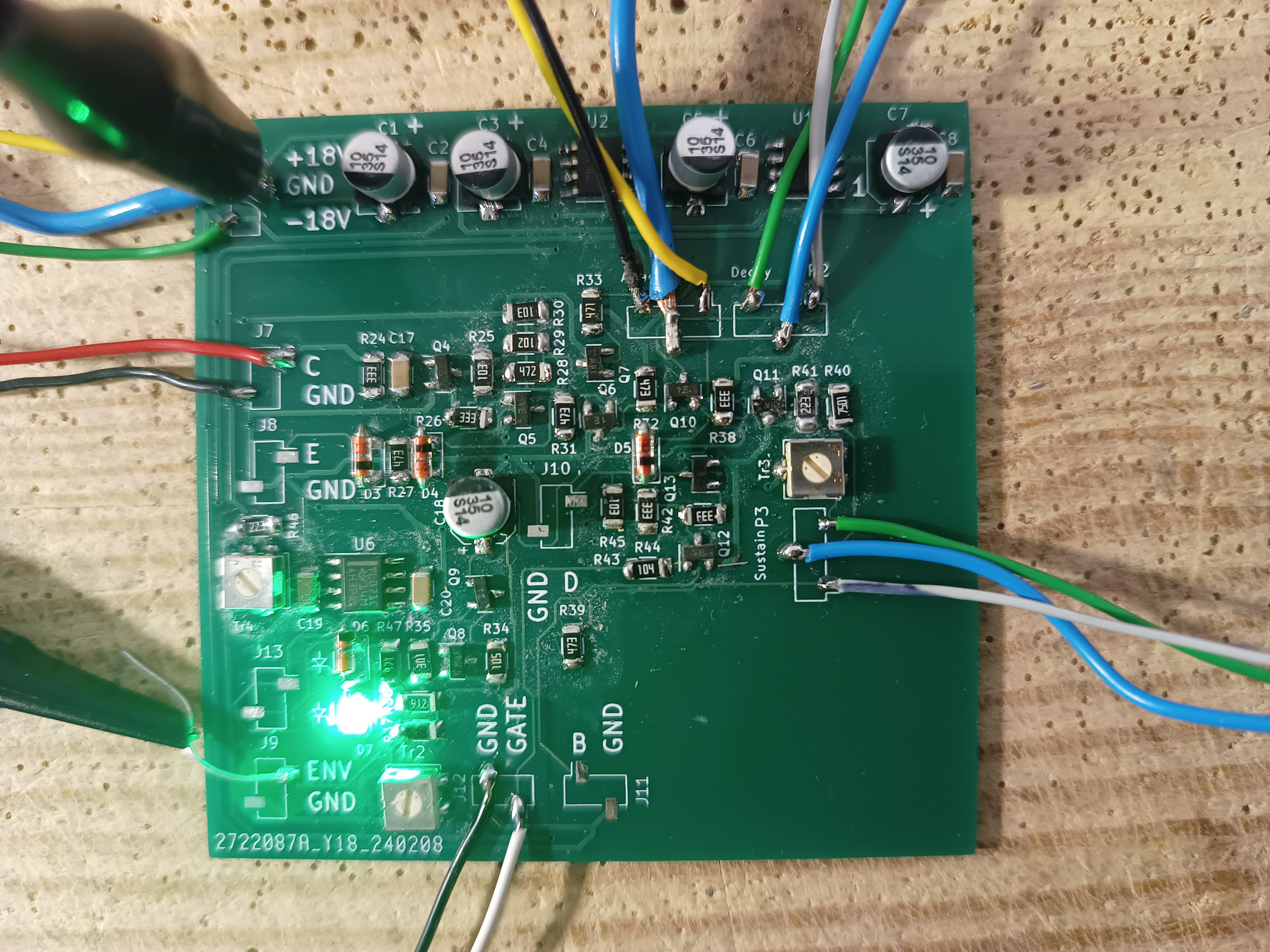
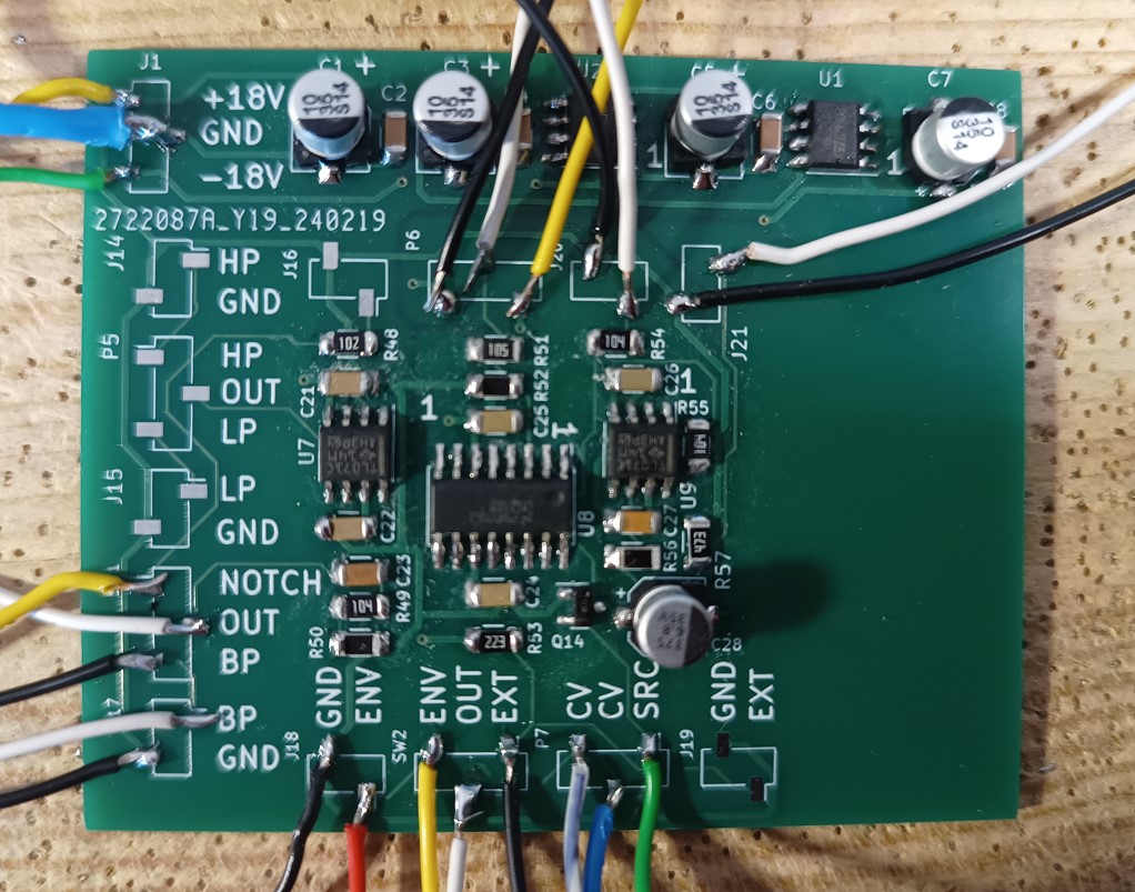
TSEM VCA ENV Hardware
| 
| |
|
|
YouTube
TSEM VCA ENV Demo