This module has two tasks in my modular system:
- Addition of a dc voltage (done by the mixer module) to an LFO modulation output signal to do a better VCA modulation (otherwise the LFO reacts only to the postive cycle of the LFO output signal).
- Creation of voltage references to check ADC inputs of Ácontroller circuits (e. g. UCVM)
Circuit:
The circuit can be found here. Attention: Clicking schemo link means accepting the DISCLAIMER on page bottom!!!
Theory of operation
The 100k pot covers a range of about -10 to +10 volts due to the two 10k resistors. With the offset trimmer you can move this range up or down.
The TL061 opamp works as an inverting amplifier where you can choose / change amplification gain with the gain trimmer.
With this two trimmers you can configure the module ranges as you like.
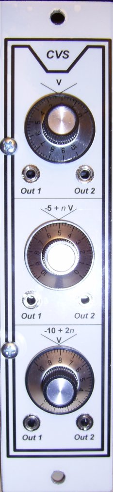
I built the circuit three times on a 100x80mm board and configured the three units as following:
- V (volt): The output voltage follows (nearly, see below) the pot value. This unit covers the range from 0 to +10 volts.
- -5 +nV: The output voltage can be computed from the pot value, e. g. selecting 5 (nearly, see below) means output = -5V + 5V = 0V. This unit covers the range from -5 to +5 volts.
- -10 +2nV: The output voltage can be computed from the pot value, e. g. selecting 8 (nearly, see below) means output = -10V + 2*8V = 6V. This unit covers the range from -10 to +10 volts.
When I calibrated the circuit(s) according the pot positions on the panel I realized a certain non linear behaviour of my linear pots.
Then I connected an identical pot to my meter, punched it thru a piece of paper, mounted a knob on top and noted the resistor values on the paper.
The result was the following drawing!
As you can see you need a lot of knob movement to reach the 10k, then you have a quite linear range about 200 degrees followed by a week rest until final position.
This means for the module that the pot graduation is just a "nearby" value. If you need precise values you have to use (expensive) precision pots or you connect a multimeter to the second output of the unit currently in use.
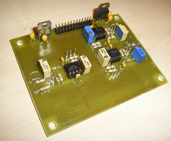
Board of the CVS module:
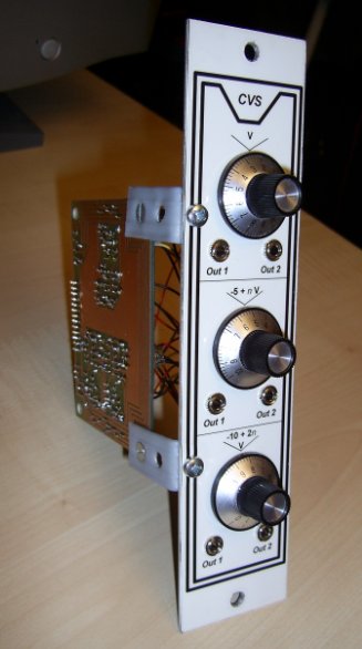
Complete module:
Sound example:
A modulation signal of an LFO becomes level shifted. This Patch duplicates a modulation signal of an LFO and puts it (one time inverted) on two VCAs after level shifting each channel with the CVS and the Mixer module. The also duplicated tone signal moves between the stereo channels then.
Reproduction hints:
None.