Click to enlarge

Click to enlarge

Click to enlarge
Click to enlarge

Click to enlarge
Click to enlarge | Click to enlarge | Click to enlarge | Click to enlarge | Click to enlarge |
|
|
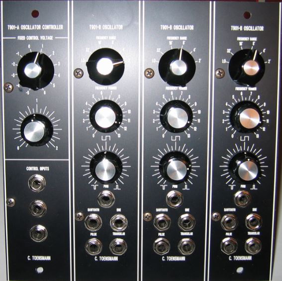
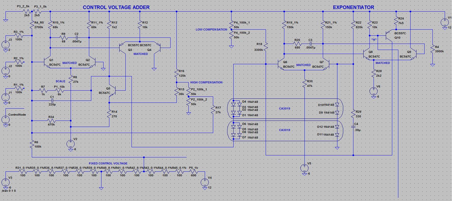
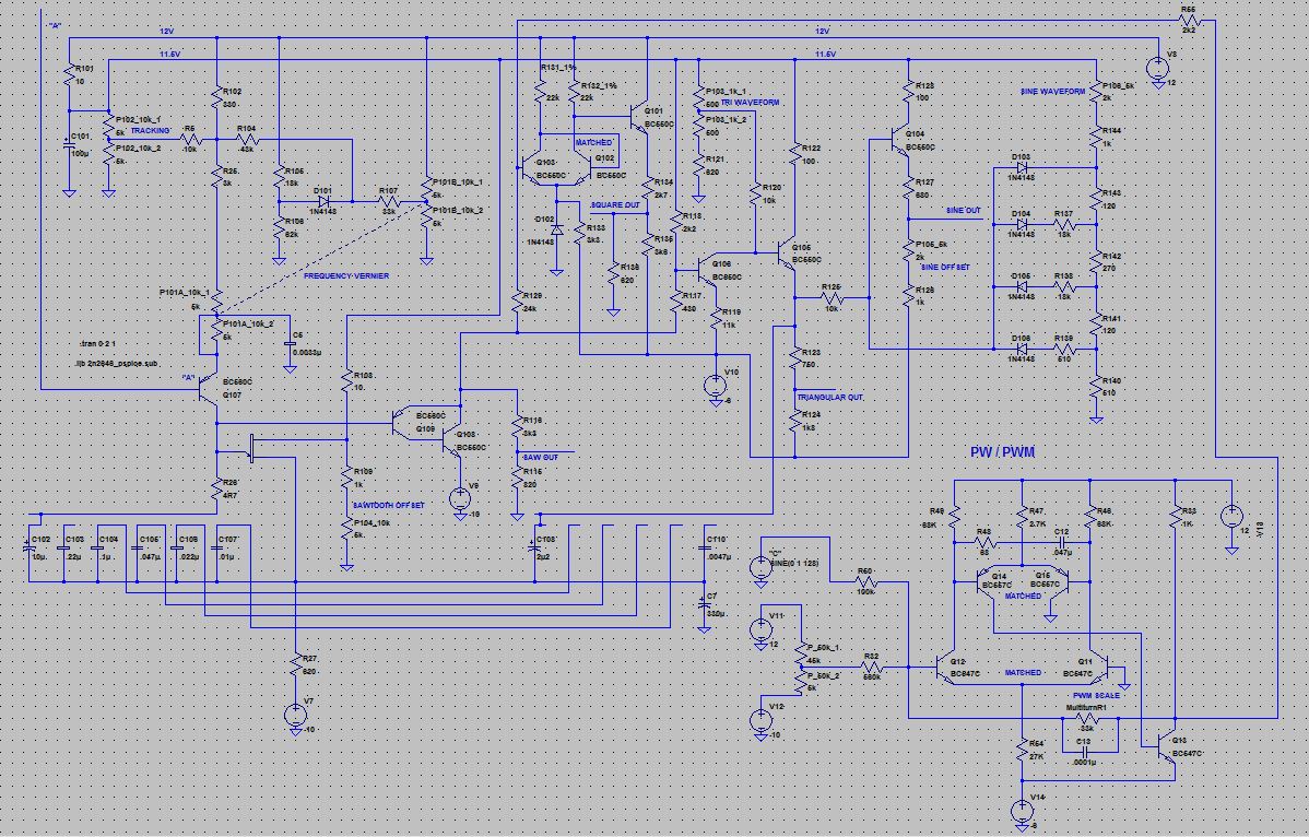
Controller On top you find a Fixed Control Voltage rotary switch - one position change changes the control voltage base for one volt. In the original module this should increase or decrease the output frequency about one octave, but in my clone the output is changed about a third only. But a change in an incoming real control voltage (from front panel CV input (see below) or from internal node connector) of one volt leads to a change of one octave indeed, so my clone operates at 1V/oct in general, but not by switching the front panel selector. First I tried to solve this mystery, but then I saw the advantage in this behaviour: a possibility of octave part selection in module tuning. So I decided to keep it this way. The second knob does a fine tuning of +/- one third of an octave. Same behavour as above, a third instead of a complete octave. And finally the three control inputs. 1V/oct characteristic. These three inputs and the internal node connector are mixed and determine the note / frequency beeing played / created. Oscillator On top you find another octave selector. Again, a position change should result in an octave change, but my clone changes the output on certain positions more than one octave, and on other positions less than one octave, depending on the integration capacitor selected by the rotary switch (see circuit description below). To avoid this I would have to do experiments with different capacitor values, but again: why should I do this? Quick changing of octaves in live performances will never be my problem, so I use it as it is, no more effort, in my studio I have enough time to calibrate my modular exactly. The Frequency Vernier knob changes the ouput octave about +/- 1 oct. Bad side effect: It changes the tracking also! The reason is obvious if you study the original circuit diagram (see circuit description below). I've not understood the concept behind this yet, perhaps someday someone explains it to me. The Pulse Width pot migrated from the controller module to the oscillator(s), as mentioned above. Little icons on the front panel show the effect of each position to the pulse width. The Pulse Witdh Modulation input (PWM) sets the pulse width depending on an input voltage. This is something the original missed, so I decided to add it as I consider this as important (see above). Finally the waveform ouputs. No waveform selector, as in other oscillators. I decided to keep it that way, as I'd run out of front panel space if I'd add an additional knob and an additional output. |
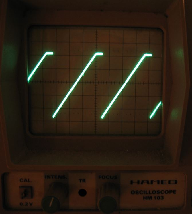
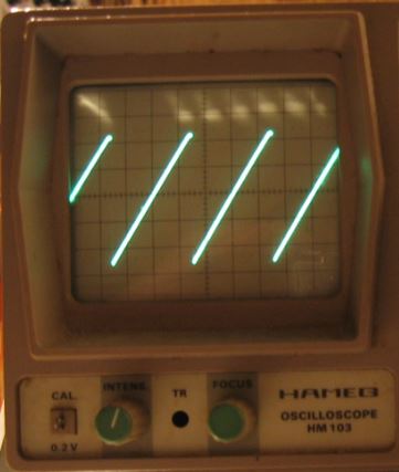 Saw (Click to enlarge) | 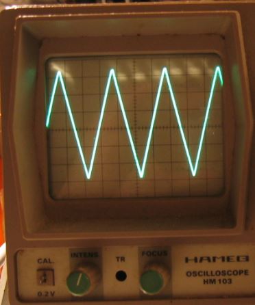 Triangle (Click to enlarge) | 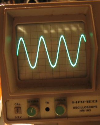 Sine (Click to enlarge) |  Pulse (Click to enlarge) |
 Click to enlarge | 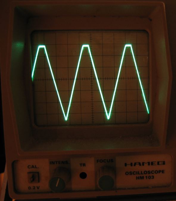 Click to enlarge | 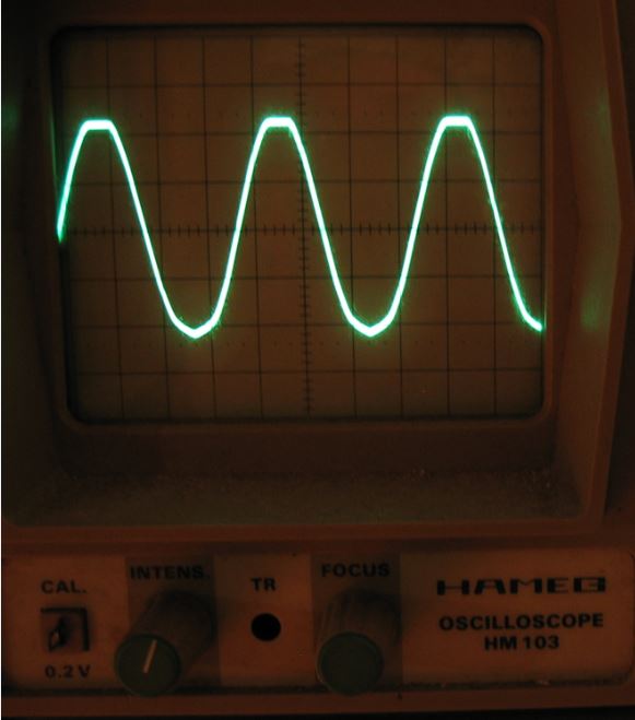 Click to enlarge | 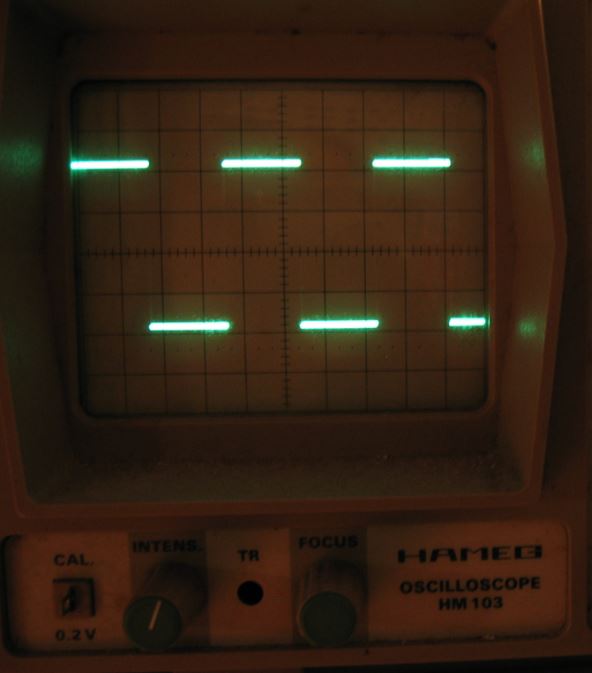 Click to enlarge |
 Click to enlarge |  Click to enlarge |
 Click to enlarge |  Click to enlarge |