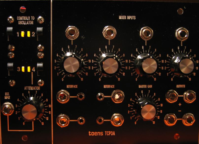
In the center one can find the INTERFACE sockets which are adapters between 6.3 and 3.5 mm plugs.
|
| The human interface of the CP3A shows the partitioning in two subunits: The control voltage router (CONTROLS TO OSCILLATOR) with EXTERNAL INPUT socket snd ATTENUATOR pot and the 4 channel mixer with MASTER GAIN and the phase inverted outputs OUT + and OUT -.
In the center one can find the INTERFACE sockets which are adapters between 6.3 and 3.5 mm plugs. |
|  Click to enlarge |
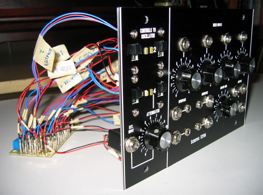 Click to enlarge | As you can see the board has to be mounted separately in the cabinet and does not have any fix connection with the front panel like the other modules have. This is typical for System 55 instruments, where the control panel modules are mounted on the cabinet bottom. | 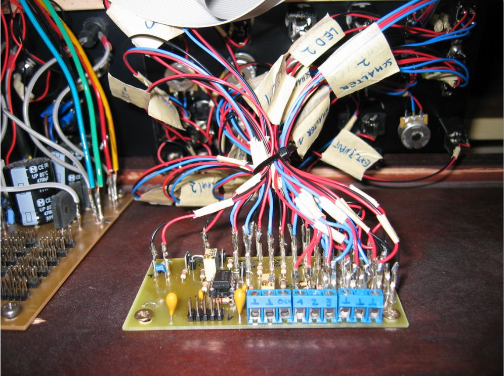 Click to enlarge |
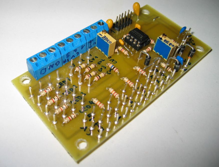
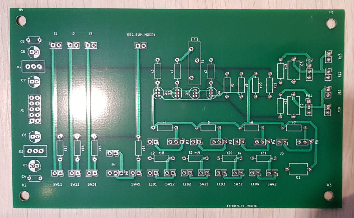 Click to enlarge | 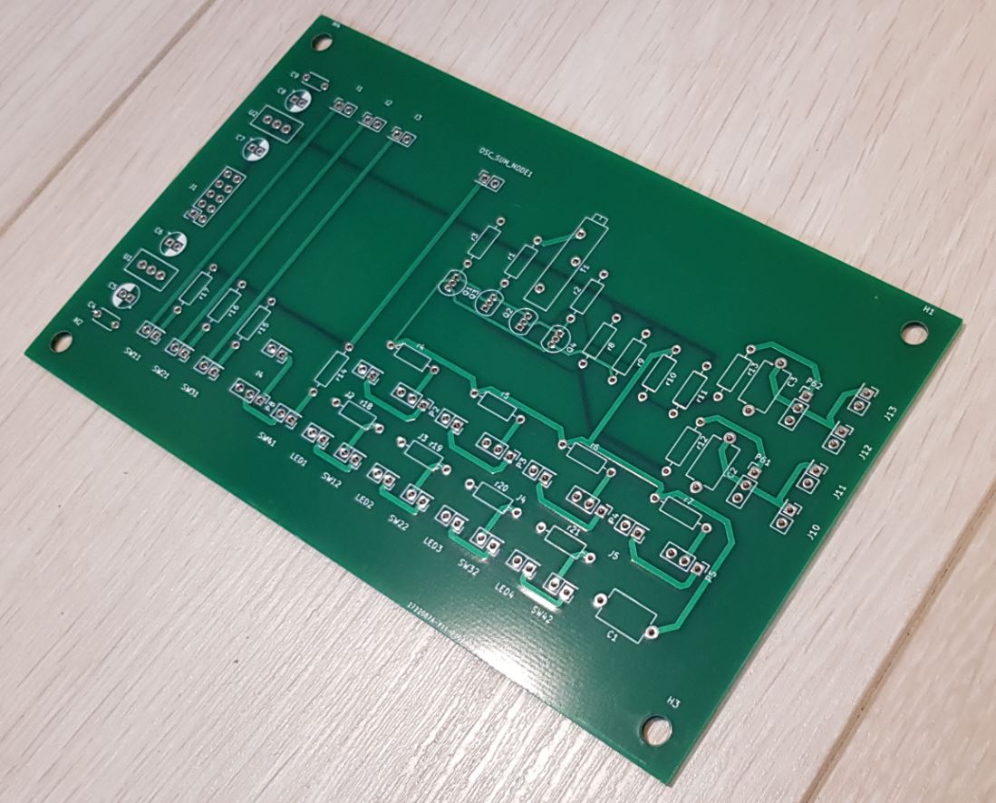 Click to enlarge | 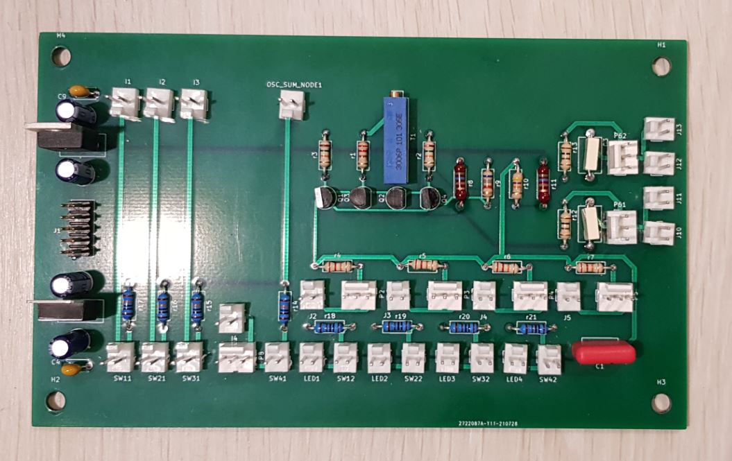 Click to enlarge | 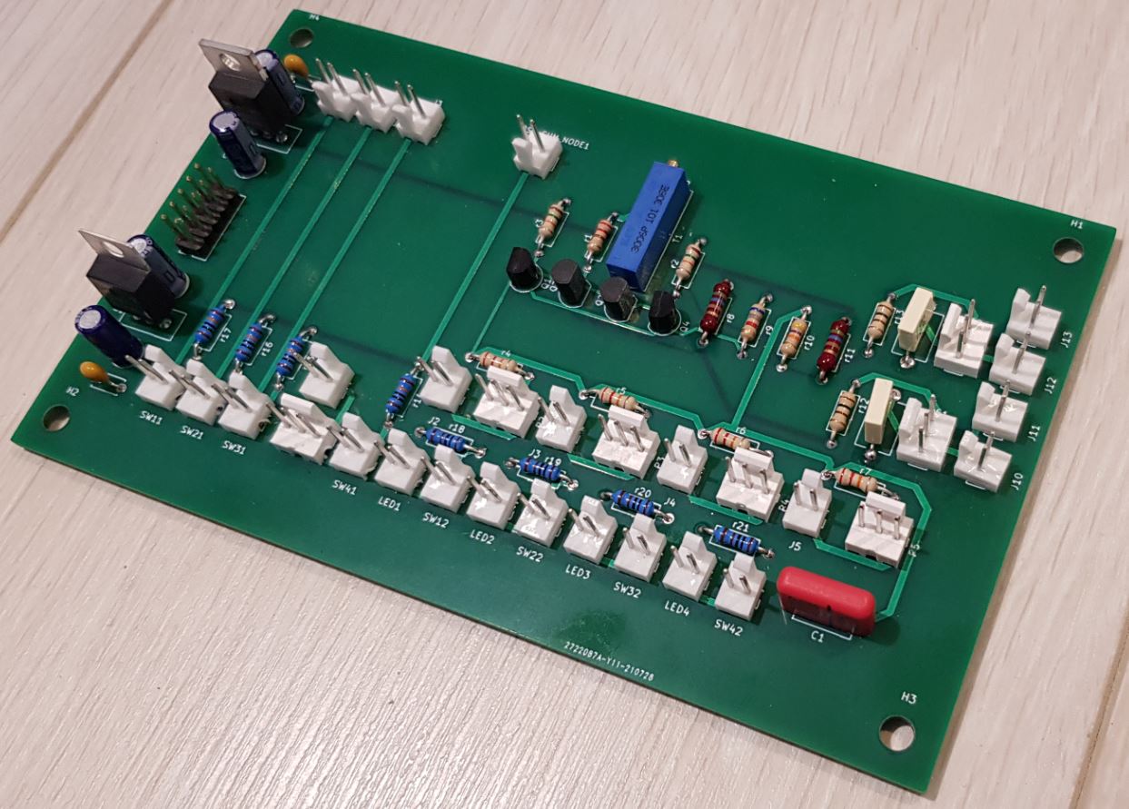 Click to enlarge | Four transistors, some resistors and capacities build this mixer, not more. The rest is IO and CV routing. |