Introduction:
This is the second module of the Moog (TM) Modular Oscillator topology which is heavily inspired by the well known Minimoog oscillator bank. And beeing a smartass as always I tried to improve and enlarge its functionality.
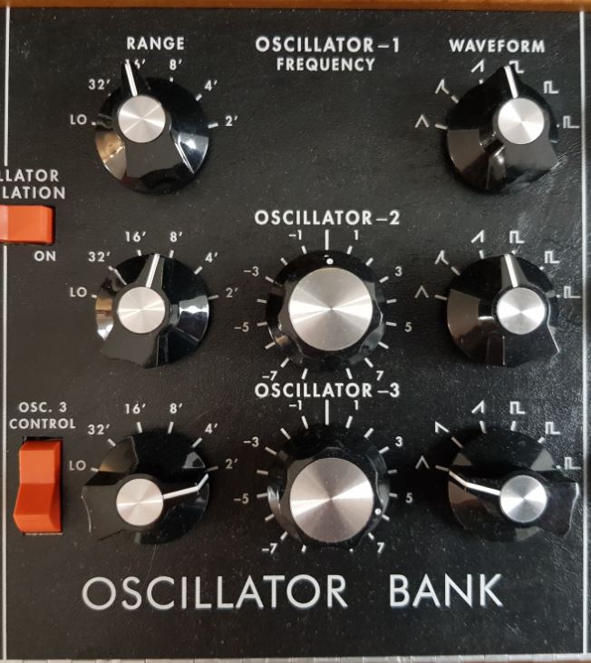 Original Minimoog Oszillator Bank | 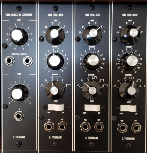 TMINI clone |
To adapt this oscillator bank to a kind of Moog System 55 concept I divided the original structure of the Minimoog Oscillator Bank in a controller section (one) and an oscillator section (three) like the 901 and the 921 oscillator topologies do. The oscillator is quite similar to the original, but each TMINIB oscillator is a separate module. It is controlled internally by a TMINIA Oscillator Controller, which provides the control voltage sum and an audio signal which can be used for oscillator synchronization purposes.
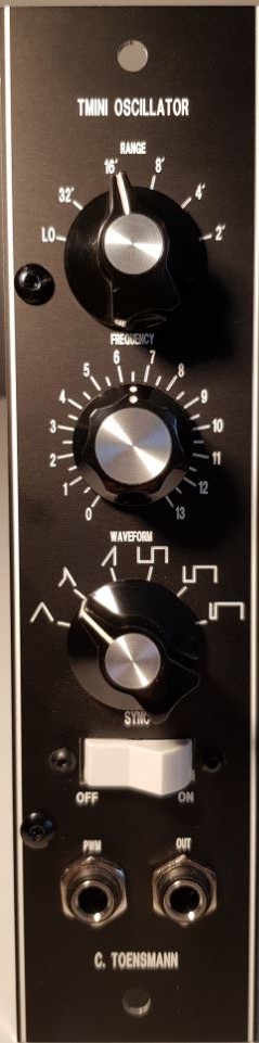
So here it is: the TMINIB Oscillator.
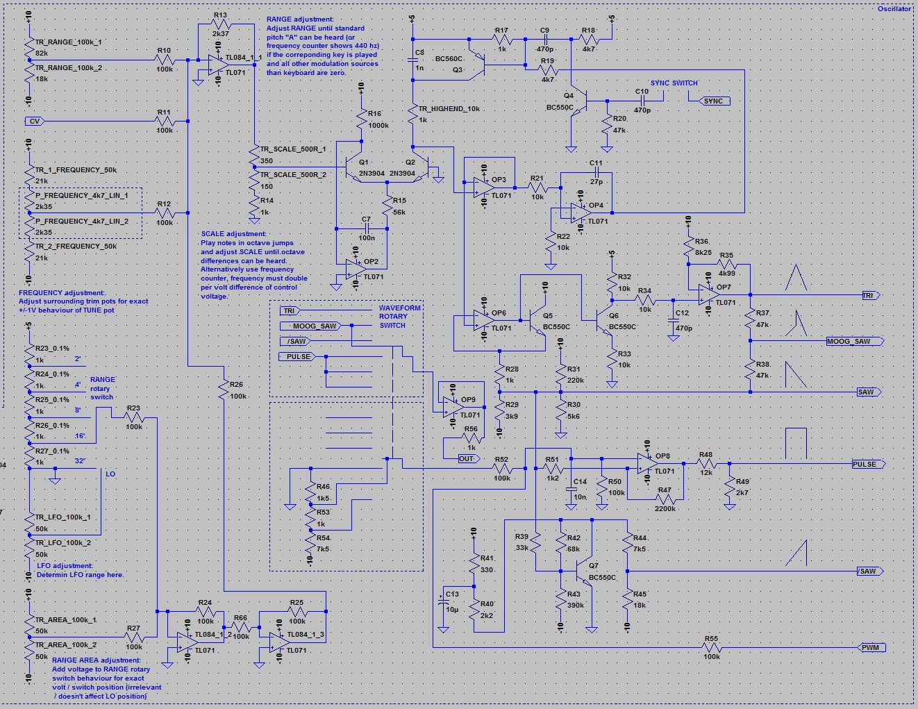
Oscillator circuit:
Schema: Clicking the schema means accepting the disclaimer on page bottom!
Control voltages: The internally provided control voltage (CV - R11), the output voltage of the FREQUENCY pot (via R12), the range trim (TR_RANGE - R10), the RANGE rotary switch (via R23) and the RANGE AREA adjustment trim (via R27) are mixed to the control voltage sum which controls the oscillator. The LO position of the RANGE switch adds a negative voltage to the sum to slow down the oscillator to LFO behaviour. This negative voltage is determined by the TR_LFO trim. The range voltages are buffered by two inverting voltage followers before being added to the control voltage sum. The RANGE AREA adjustment trim adds or subtracts a voltage to the range voltages to determine the range behaviour in total.
|
Saw core: The saw core is based on a heated 3046 transistor array. It is the base for all subtractive synthesis.
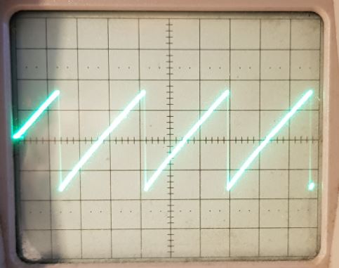
The control voltage sum is reduced by an inverting amplifier and the TR_SCALE trim to hit the exponential Ub => Ice response area of Q1. The exact V / Oct behaviour is determined here. See scale demonstration video. Please note: The transistor type 2N3904 for Q1, Q2 is chosen for LTSpice simulation purposes only. The real prototype works with a CA3046 transistor array! OP2 works as current sink for the exponentiator. The exponentiator works as differential amplifier and determines the linear loading current of the capacitor C8. The voltage at the collector of Q2 represents a falling saw waveform / ramp. It is buffered by a non inverting voltage follower (OP 3) and integrated by OP4 and C11 to a negative reset pulse when the ramp voltage reaches 0V. This opens the PNP transistor Q3 via R19, which resets the charge of the capacitor C8 back to 5V, and the cycle restarts. The saw is also buffered by OP6 and Q5, level shifted by R28 and R29 and then provided at the saw output terminal. Additionally the saw is provided as inverted waveform, which is selectable on oscillator one and two (see original Minimoog oscillator bank). This is done with Q7 working as inverter. The original saw ist selectable only on oscillator three, instead of the Moog Saw. The saw core can be adapted to synchronisation by providing an audio signal at the TMINIA oscillator controller SYNC IN and setting the SYNC switch to "ON". The internally provided audio signal is integrated via C10 to pulses which open Q4, which works as inverter. The inverted pulses work as additional reset pulses at the base of Q3 (via C9), so the saw creation is disturbed. See video for details. |
Wave shaping:
|
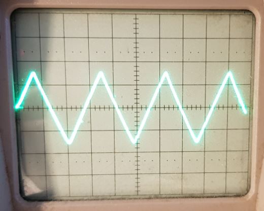
Triangle: Q6 also works as triangle shaper, as the lower half of the incoming saw is passing the Qbc transistor internal diode in opposite direction and is folded upwards. The resulting triangle voltage at the collector of Q6 is cleaned, buffered and level shiftet by C12 and OP7 and is provided at the triangle output terminal. The result is a smooth, dark sound. |
|
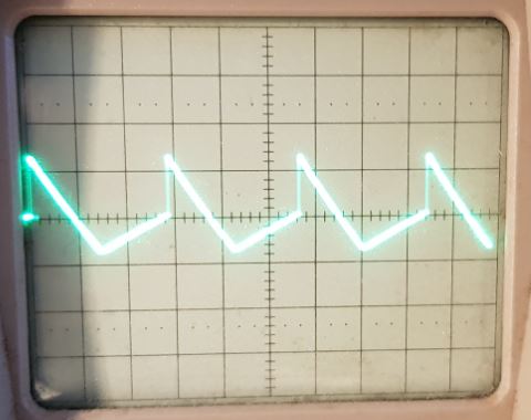
Moog Saw: The famous Moog Minimoog waveform. It is created by mixing the triangle with the saw via R37 and R38. The result is a very smooth sound with a lower and a higher spectrum. |
|
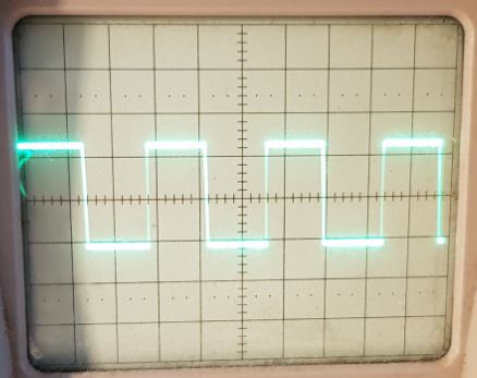
Symmetrical Square (50% - 50%): The saw is fed into the comparator OP8 via R51 compared to a reference voltage which determins the pulse width. The symmetrical square (0V reference voltage) creates a quite hollow sound. |
|
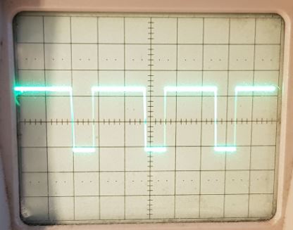
Square (70% - 30%): With a lower reference voltage (-1.5V) the square becomes more asymmetrical and creates a sound with a higher and thinner frequency spectrum. |
|
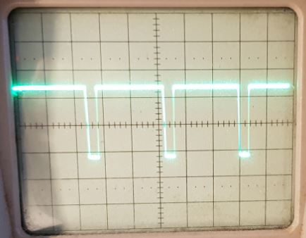
Square (85% - 15%): With a reference voltage of -2.5V the square becomes even more asymmetrical like a needle and creates a very high and thin sound. |
|
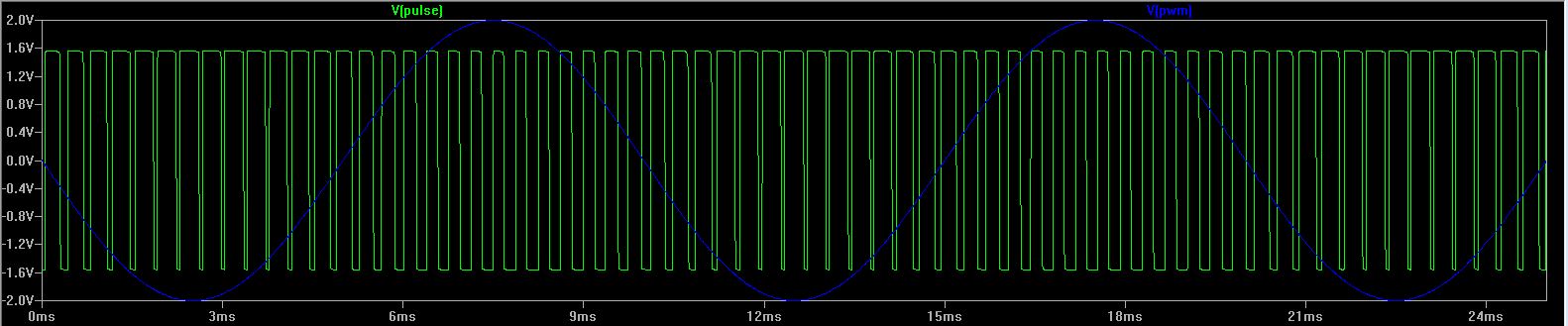
| Pulse Width Modulation: The simulation plot shows the PWM function of the oscillator. The PWM input (blue) is mixed to the pulse width reference voltage of the WAVEFORM rotary switch via R55. |
Tranistor array heating circuit:
Schema: Clicking the schema means accepting the disclaimer on page bottom!
The 3046 array is heated by the current of Q9. The amount of current is determined by the voltage at the base of Q10 working as temperature sensor, influenced by the current of Q9, so a self regulating mechanism ensures a constant chip temperature of the 3046. The temperature is determined by the TR_TC trim, which provides a reference voltage for the comparator OP10. C15 suppresses parasitic oscillation of the temperature control. Q8, Q9 and Q10 are 3046 internal transistors of course, labeled with 2N3904 for simulation purposes only. Q8 provides the negative reference of the substrate connection.
Setup and Test:
All setup and test descriptions can be found at the corresponding sections of the circuit sheets.
Differences to the original:
- Oscillator synchronization added
- (Real) pulse width modulation added
- (nearly) 5 octave range
- No part replacement at all, as this is a new circuit
Frontend:
- RANGE rotary switch: Selects the foot level of the oscillator frequency, except LO which creates LFO behaviour of the oscillator(sub sub sub audio range)
- FREQUENCY pot: Tunes the oscillator dependent on the adjusted amount (see circuit)
- WAVEFORM selector: Selects six of the seven waveforms provided by the oscillator, in this case triangle, Moog Saw, rising saw, symmetrical square, square (70% - 30%), square (85% - 15%). Oscillator three of the bank provides falling saw instead of Moog Saw
- SYNC switch: ON routes the SYNC audio signal internally provided by the TMINIA oscillator controller to the sync input of the saw core
- PWM: Input for pulse width modulation
- OUT: Output for selected waveform (oscillator output)
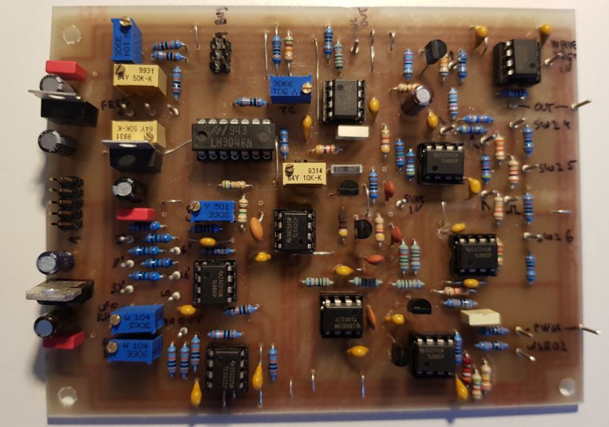
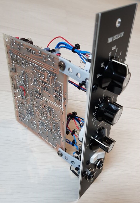
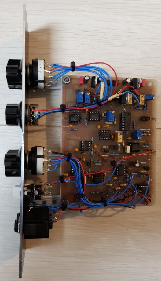
TMINIB Module
|
|
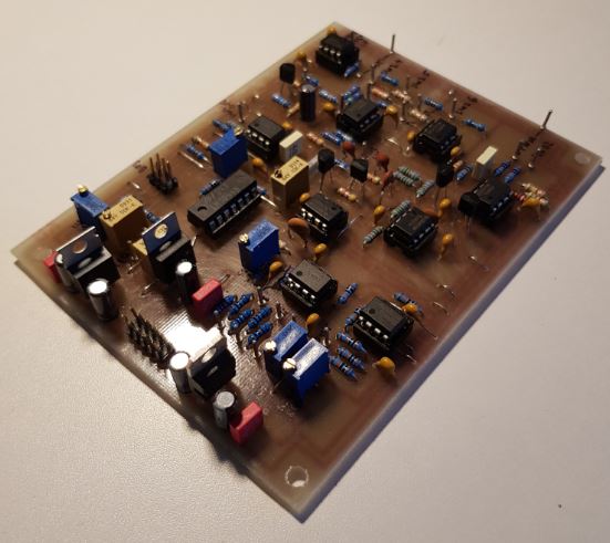
| 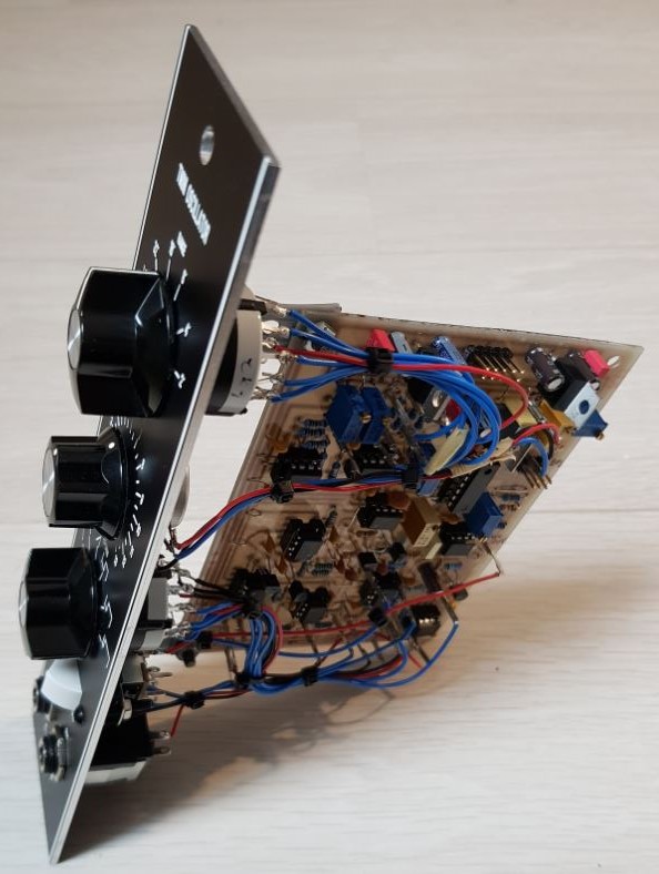
|
| 
|
Videos
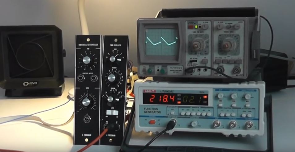 TMINI scale demonstration with Moog Saw waveform | 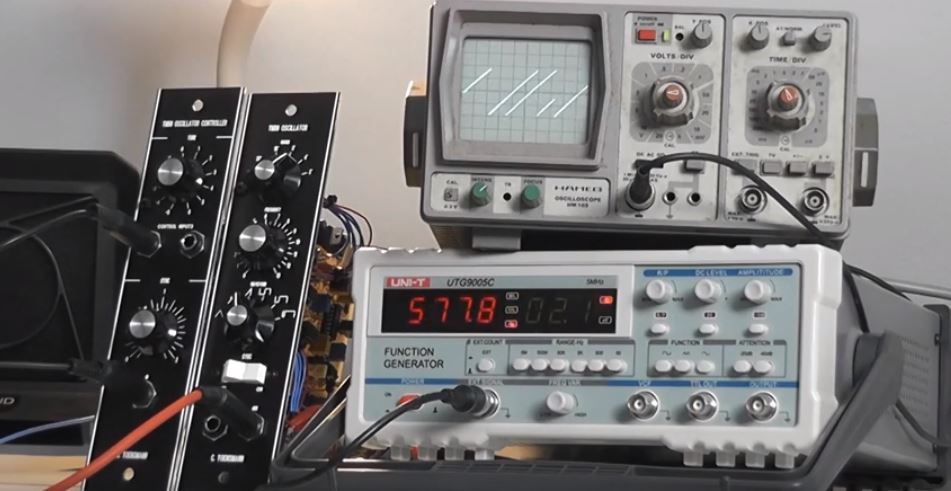 TMINI sync demonstration - | 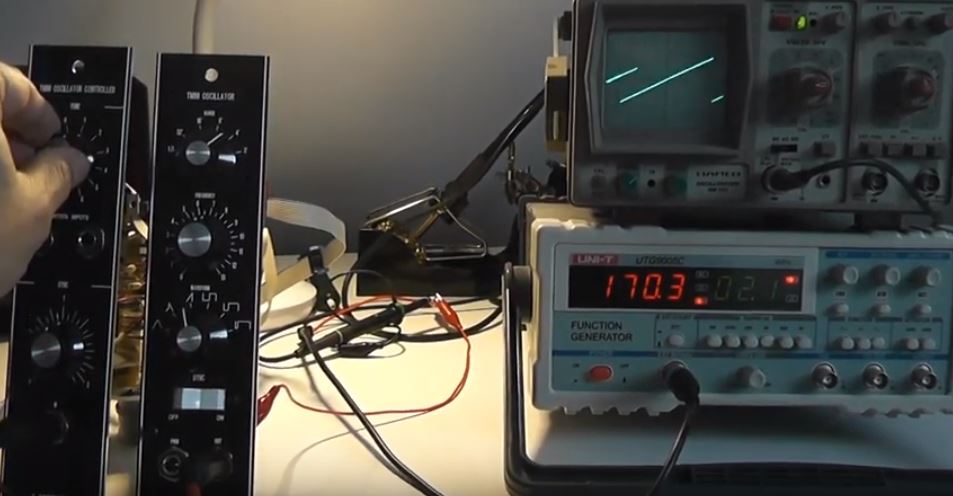 TMINI test with Moog System 55 clone - |