Introduction:
This is the first module of a Moog (TM) Modular Oscillator topology which is heavily inspired by the well known Minimoog oscillator bank. And beeing a wise guy as always I tried to improve and enlarge its functionality.
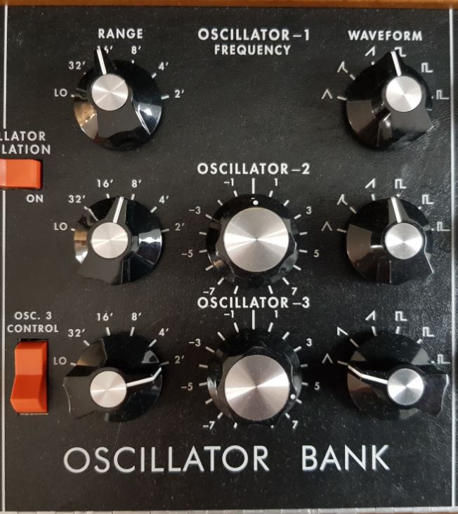 Original Minimoog Oszillator Bank | 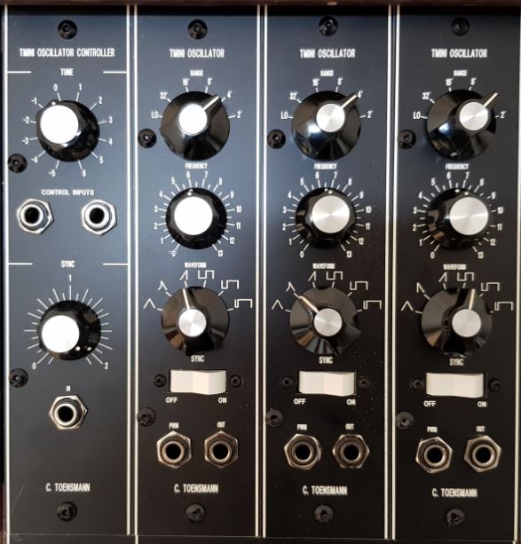 TMINI clone |
To adapt this oscillator bank to a kind of Moog System 55 concept I divided the original structure of the Minimoog Oscillator Bank in a controller section (one) and an oscillator section (three) like the 901 and the 921 oscillator topologies do. But in this case the controller or driver is a primitive, just a control voltage mixer with capability of adding a fixed control voltage and an input stage for external signals for oscillator synch purposes, which is just routed to the oscillators internally (see TMINIB Oscillator).
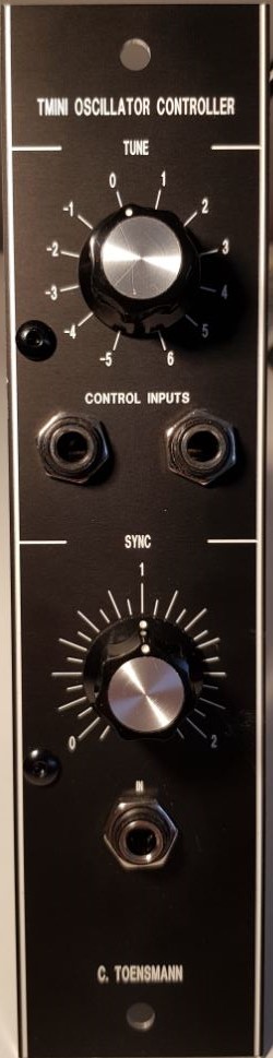
So here it is: the TMINIA Oscillator Controller.
Circuit:
Schema: Clicking the schema means accepting the disclaimer on page bottom!
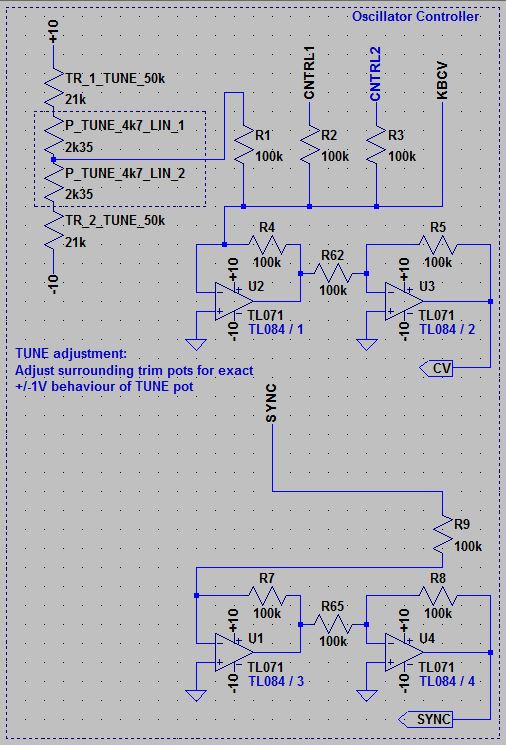
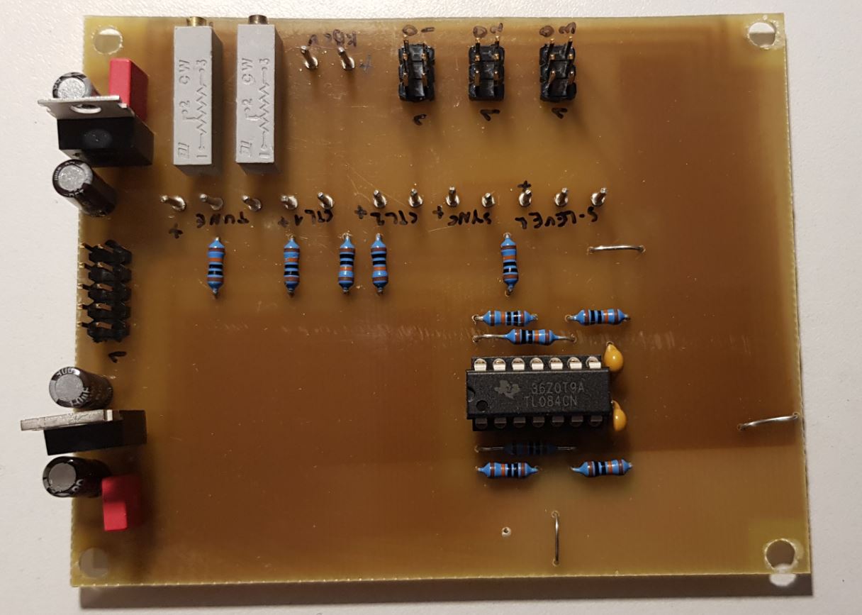
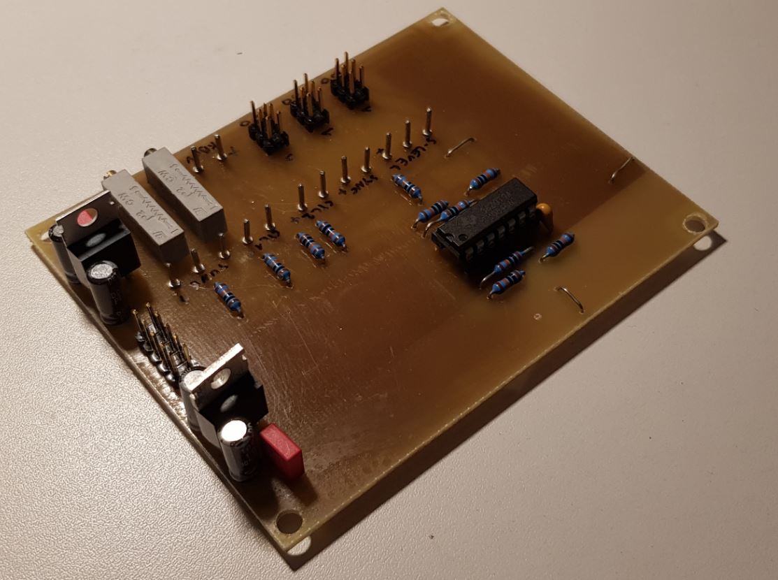
Two frequency control voltage input jacks (6.3mm, R2 - R3) are mixed with a voltage provided by the frequency control pot (P_TUNE)of the front panel and an internally provided control voltage coming from the TCP3A mixer (KBCV) which belongs to this controller bank (according to the System 55 concept each oscillator bank has its own CP3A CV mixer). The amount of control voltage which can be added or subtracted (center position of pot = +/-0) is determined by the surrounding trim pots (TR_1_TUNE and TR_2_TUNE), as all this works as voltage divider. An additional benefit is the possibility to compensate potentiometer tolerances by adjusting the amount of voltage added to e.g. exact +/-1V in fully clockwise or counter-clockwise adjusted position.
Two inverting amplifier (U2 and U3) provide the control voltage mix internally to connected TMINIB oscillators.
The SYNC IN jack (6.3mm, R9) is buffered by two inverting amplifier (U1 and U4) and provided also internally to connected oscillators. The input level of the synchronisation audio signal can be determined by a pot as shown on the prototype front panel, but the amplitude does not really affect the sync function as long as it is high enough, so I removed the level pot from the Circuit: Clicking the schema means accepting the disclaimer on page bottom!.
Setup and Test:
Just the behaviour of the TUNE knob as described above (refer to circuit for details).
Differences to the original:
- Oscillator synchronization added
- (Real) pulse width modulation added
- (nearly) 5 octave range
- No part replacement at all, as this is a new circuit
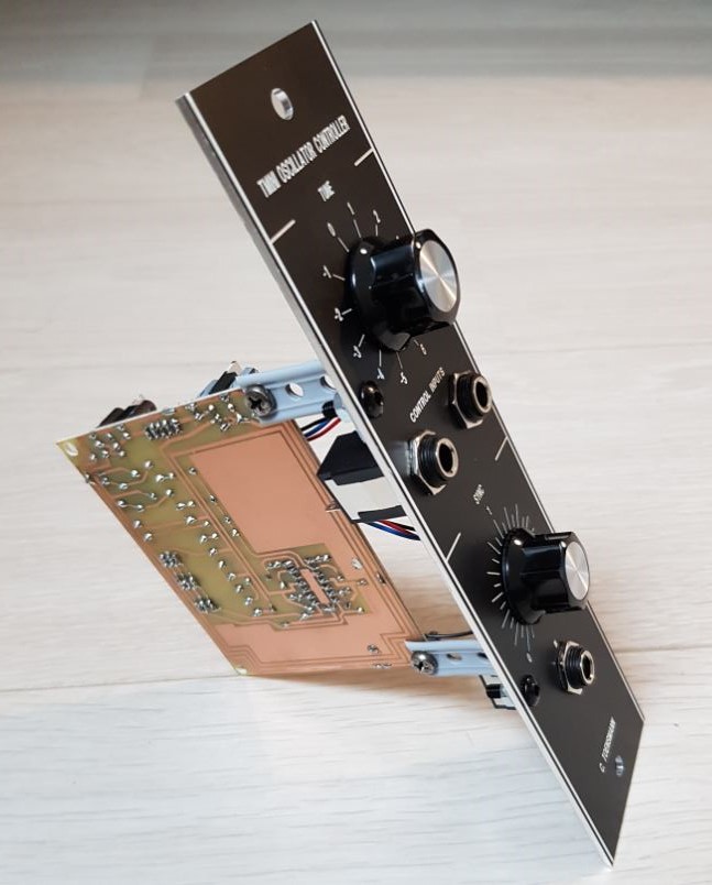
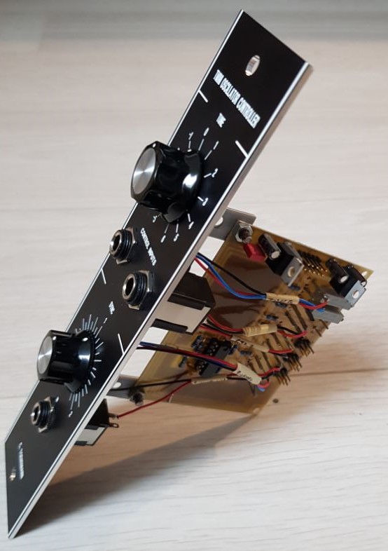
Frontend:
- Tune control pot: Adds control voltage to frequency controlling voltage sum. Can be adjusted widely, but my recommendation is to set up +/- 1V behaviour, meaning +/- 1 octave frequency change for the oscillators.
- SYNC IN: Input for audio signals the oscillators can be synched to.
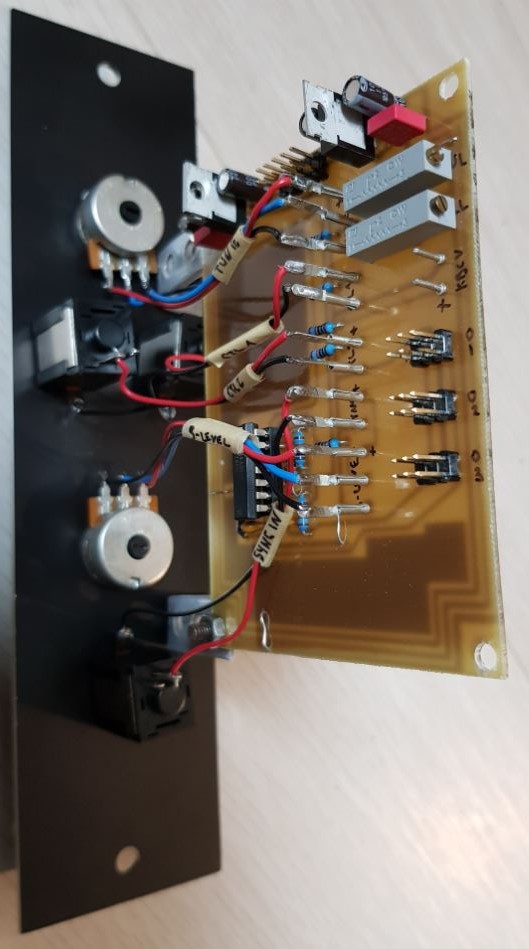
TMINIA Module
|
|
| 
|
| 
|