This is the second filter module I built for my modular. The first one is the 12db Formant VCF module from the book MSS2000 from HaJo Helmstedt. The new VCF module here is also based on this book, but in that book version the signal buffer in the transistor ladder output stage which is postulated by the Moog patent is missing. That's why I added parts of the filter circuit of Rick Jansen and the ASM2 which inlude this stage.
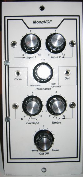
The filter has two signal inputs, a control voltage input, a resonance level pot, two mudulation inputs and a CutOff adjust.
The resonance can be increased / adjusted up to self oscillation of the filter. This self made signal is a sinus signal. In this mode the filter can be used as a sinus vco, but there is no temperature compensation of the expo converter, so there is no volt / octave stability in this "VCO". This temperature compensation is provided in the ASM2 circuit, but I did not include it in my version.
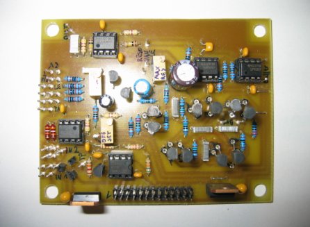
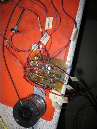
Board of the Moog VCF
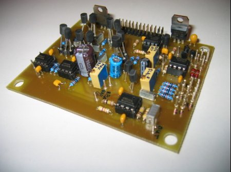
I also added the transistor test circuit of HaJo Helmstedt for selection of the transistors of the ladder part (lower left side) and beeing a good son I selected the first set of transistors as postulated. But what can I say, after killing some transistors during the module tests I used a non selected set of transistors and the filter sounded the same way as before. Then I decided to skip transistor analysis (the purists can do that, if they like).
Comparism of the filter scope pictures
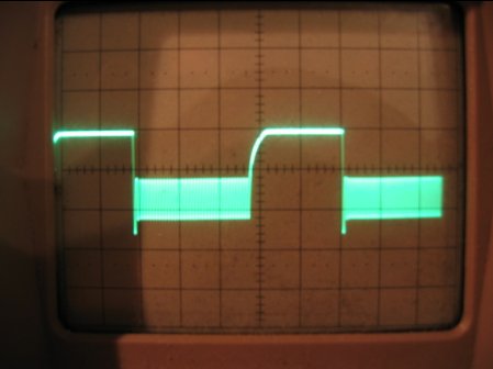
Output 12db State-Variable-Filter
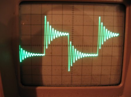
Output Moog VCF
Obviously the resonance of the Moog VCF occurs only in the lower half of a wave cycle. I don't know the reason for it (perhaps the reason is the fitting point of the resonance signal on one side of the transistor ladder?). I don't think that I made any severe mistakes on the board as the filter does what it is expected to to. Also the self oscillation sinus is a quite clean sinus with some minor narrow parts in the phases between 90 and 180 degrees and between 270 and 360 degrees.
Update 18.07.2006: In the meantime I built another version of the Moog filter - this time closer to the book of HaJo Helmstedt - and this module works more as expected. The output signal of a square input with high resonance looks like the picture of the 12db VCF, just a little bit denser. The module still sounds a little bit bity, but with resonance close to self oscillation the sound is much better / smoother than my (modified) first version of the moog filter.
Schematic:
I mainly used the circuit of the book "Formant Pro MSS2000" by HaJo Helmstedt and added some parts of the more Moog like circuits of:
Sound Examples:
Full resonance together with an input signal sounds very distorted and I don't like it. The best sound can be achieved shortly before self oscillation.
Reproduction hints:
If you follow my hero Robert Moog and buffer the ladder output you have to do some experiments with the amplification factor of the difference amplifier of the output stage to achieve best results. Consider: The less amplification, the less self noise of the filter. You have to find the lowest amplification where the filter still can be put into self oscillation.