Introduction:
Chapter 1 and 3 of my Oberheim-SEM-Clone-2-SMD - activities cover the LFO - and the ENV - sub function of the Oberheim SEM. Origininally just a feasibility study, I added them into my third modular system as combination module now, meaning a module with two functions, because if you build something, you should use it...
The TSEM LFO ENV:
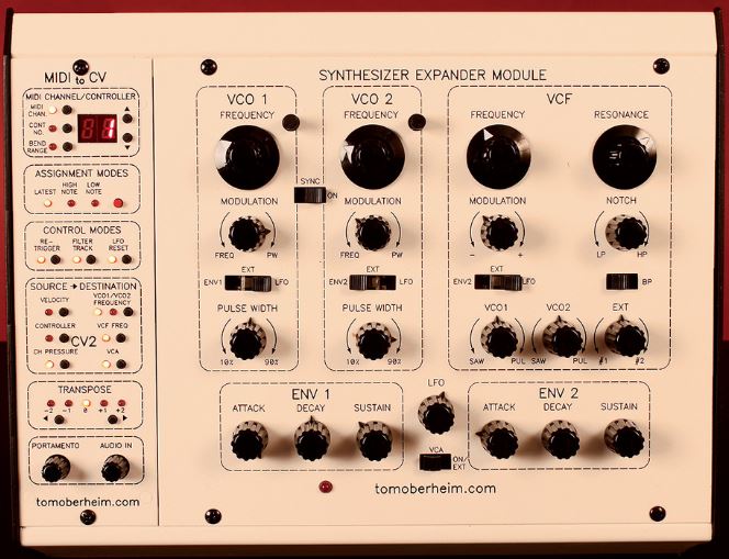
If you compare my clone with the original SEM (see below), you see the additional control elements and jacks of the front panel, which the original does not show, immediately. These are the outer representations of the inner connections of the Oberheim SEM which don't have to be exposed there obviously. The TSEM LFO ENV as stand-alone module must do that obviously, to be used properly.
| The TSEM LFO ENV: | The original: | |
|
| ---------------------------- | 
|
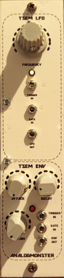
As you can see, the only control element of the LFO within the original SEM is just a pot, nothing more, not as sub function indicated with a dotted oval like other sub functions. The modulation targets of the LFO can be selected in different sub functions on the other hand. The VCO offers LFO based frequency modulation and pulse width modulation, and the VCF offers LFO based modulation of the CUTOFF adjustment.
The ENV sub functions on the other hand are visible as such.
ENV:
Please refer to TSEM VCA ENV Combination Module for my ENV clone documentation.
LFO:
The LFO kernel of the Oberheim SEM sub function follows a standard architecture (see below circuit description), but there are addons implemented.
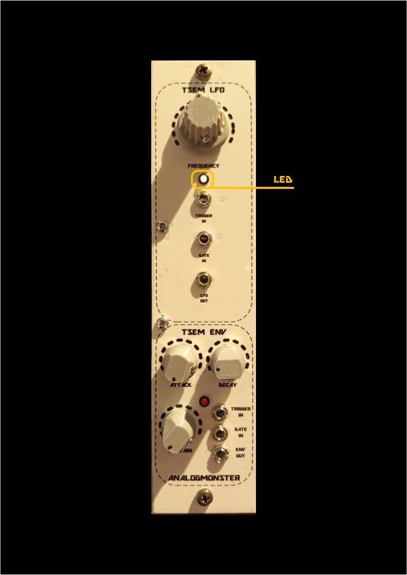
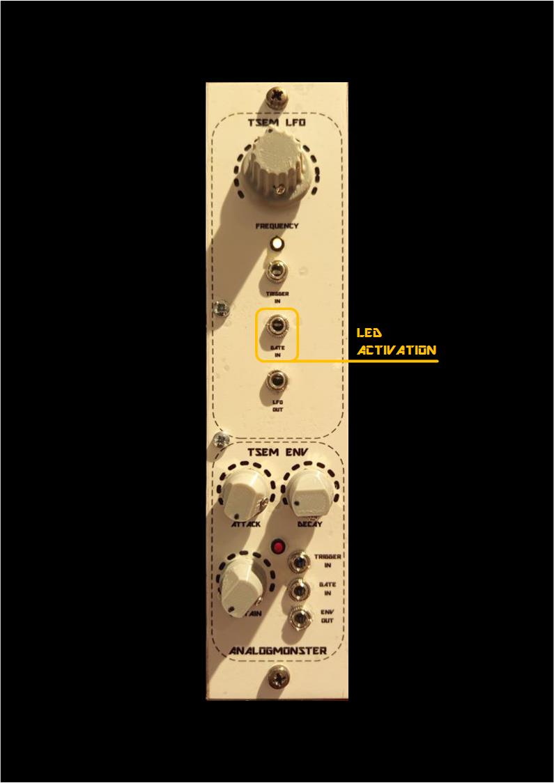
What the original does not provide, is a display LED to show the LFO activity, and a corresponding GATE input jack. If you use the last, the LED is switched on and off following the GATE input. If the LFO used in a SEM enclosure, you can indicate the activation of this SEM voice in a polyphonic context, like a GATE display. In this case the LED has two tasks, displaying the LFO frequency and displaying the GATE activity.
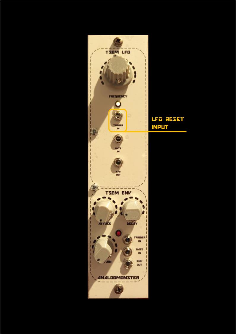
According to the original circuit you can trigger the LFO as well, meaning an enforcement of the LFO start with a reset. I don't know whether this is used in an original SEM in any form or under which circumstances, and as I am not owner of an original SEM or a 4 voice instrument I could not check out that.
But this gimmick works indeed, so I provided an TRIGGER input jack for my clone to activate this reset, just to be sure.
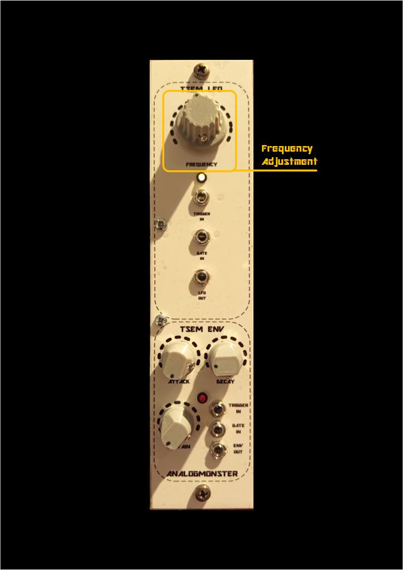
LFO Human Interface
| 
| 
|
| 
|
Schematics:
- Please refer to TSEM VCA ENV Combination Module for my ENV clone documentation.
- KiCad - Schema LFO
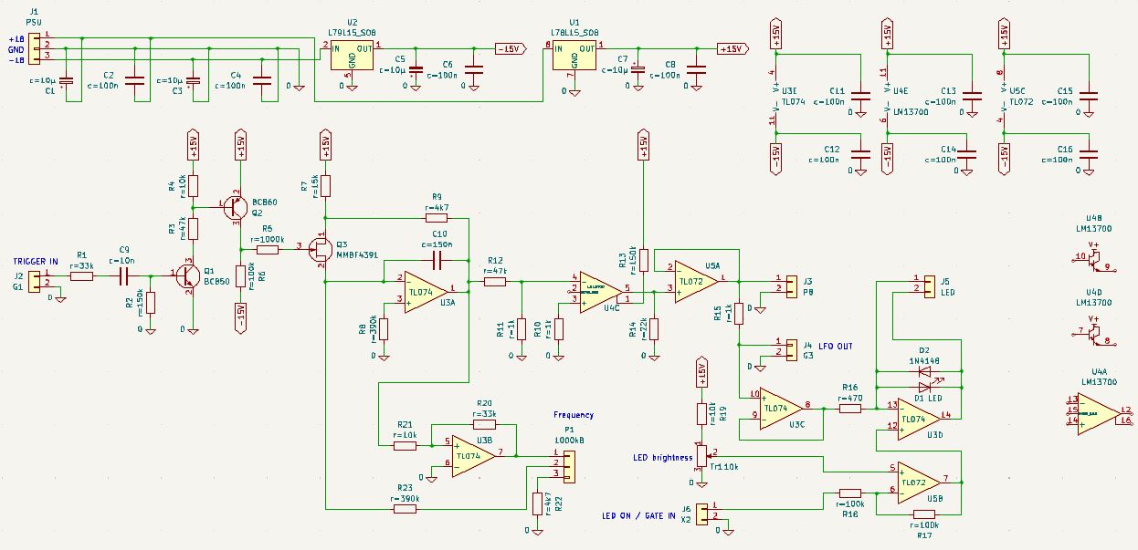
The original circuit elements which are documented in Oberheim SEM service manuals can be found easily in my clone as well.
The LFO is basically built around the integrator U3A, R8 and C10. The integrator output is a triangle signal. The frequency is determined with P1.
The triangle output signal can be reset into a defined starter position with the rising edge of a "TRIGGER IN" input signal(square). The edge is converted into a short pulse with R1 and C9, which opens Q1 and Q2. The last opens the FET Q3, and the integration capacitor C10 is charged immediately.
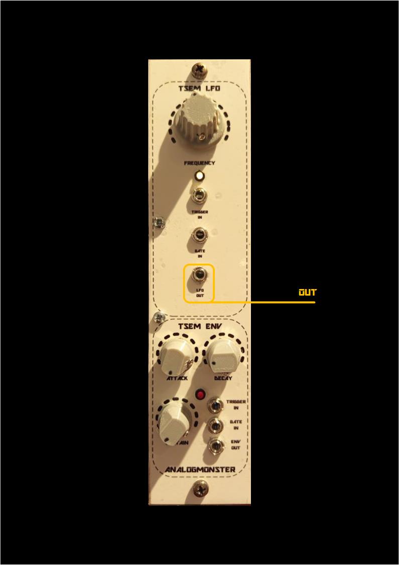
The OTA LM13700 is overdriven by a constant current via R13 and converts the incoming triangle in an outgoing sine. This sine is provided at the internal and external terminals (J3 and J4 ("LFO OUT")) and passed to the LED display around opamp U3D.
The LED brighness can be adjusted manually with trimmer TR1 "onboard" and can be switched on and off externally with the terminal J6 ("LED ON / GATE IN"), if you want to abuse the LFO as GATE display.
YouTube
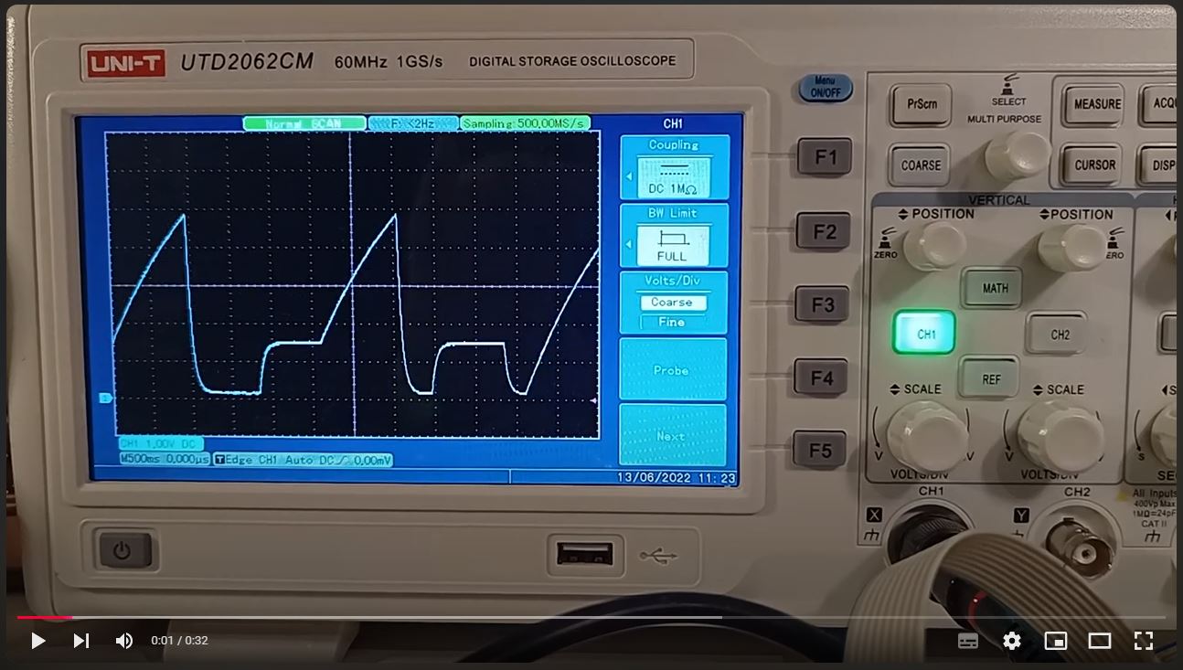
TSEM ENV Gates'n Triggers Demo