Introduction:
Before I started to build sound creating or sound forming functions I provided an output interface. So whatever will happen inside the TyCoon will have a dedicated interface to the outer world when implemented.
The reference for the TyCoon, the Synton Syrinx, provides just a monophonic VCA output as interface for the outside. But as the sound of the Syrinx is that powerful, I decided to offer a more complex stereo panner as output, which fulfils all wishes for complex output handling of different sound sources within an instrument.
I developed the circuit for my Moog System 55 Clone Project as output mixer and panner. In the modular world you need something where you can mix different sound sources and place the result somewhere in stereo space. That was the module idea, and why not use it for a keyboard synthesizer as well?
Here a functional overview of the stereo panner:
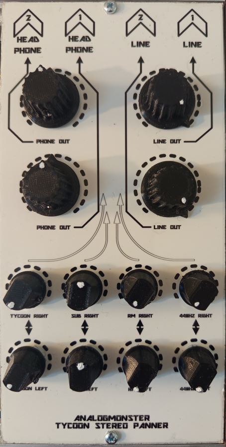
- 4 stereo input channels
- 4 x 2 monophonic channel mixer
- 2 stereo headphone outputs with volume control
- 2 stereo line outputs with volume control
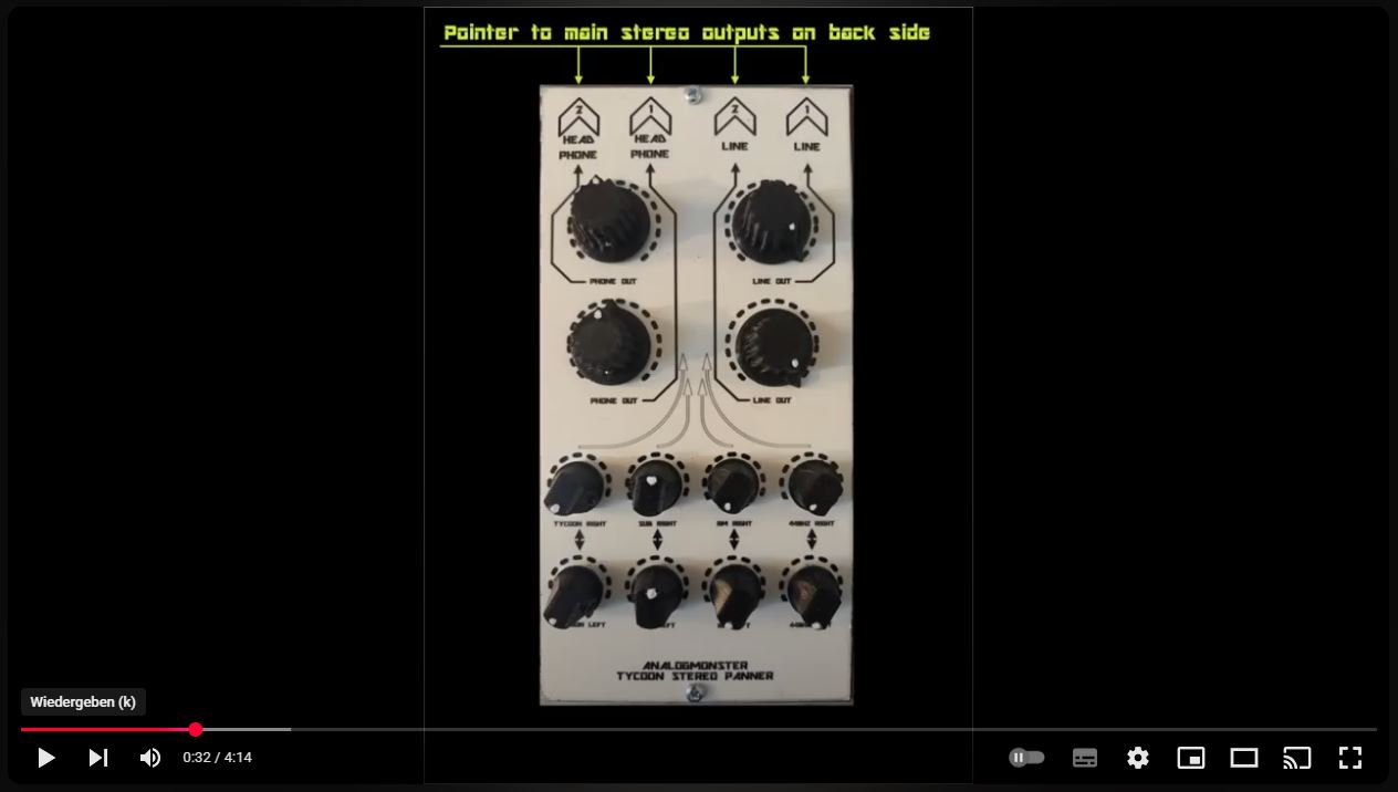
Human interface (top down)
- Arrow pointer to the 6.3 mm stereo jack bushes of the output channels on the synthesizer back
- Master volume pots for the stereo output channels
- Level adjustment pots for each input channel, divided in right and left adjustment for the stereo outputs
Click to open
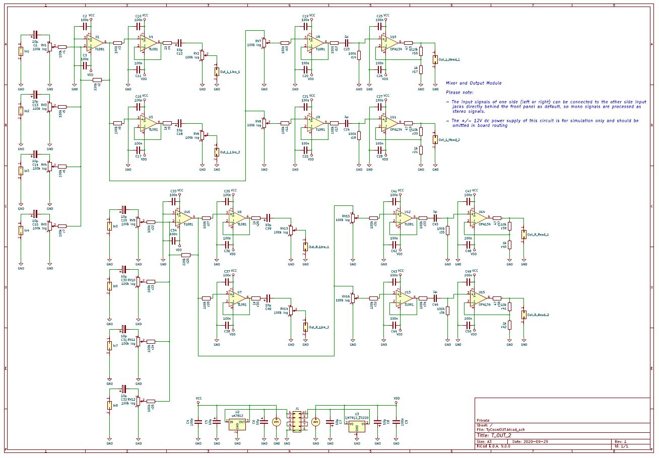
There are 8 monophonic ac coupled input channels IN 1 - IN 8 (C1, C13 - C15, C29 - C32) . They are level adjusted by pots (RV1, RV3 - RV5, RV9 - RV12).
The input channel group for the left stereo side is mixed and pre-amplified with factor 1:2.2 by U1 and r2.
The pre-amp output is provided at the left line outputs Out_L_Line_1 and 2 via the voltage followers U4 and 5, again ac coupled (C12, C18), r4 and r9 and the stereo volume pots RV2 / RV6 for LINE OUT 1 and 2 left side.
Additionally the pre-amp output is provided at the corresponding headphone output channels Out_L_Head_1 and 2 via the stereo volume pots RV7 and 8, the voltage followers U8 and 9 and ac coupled (C23, C24) at the non-inverting amplifiers U10 and 11.
The headphone circuit is "borrowed" from a portable CD player circuitry which forms a virtual ground and the correct output impedance for headphones.
All elements from the left stereo side are repeated in the lower schema half for the right side.