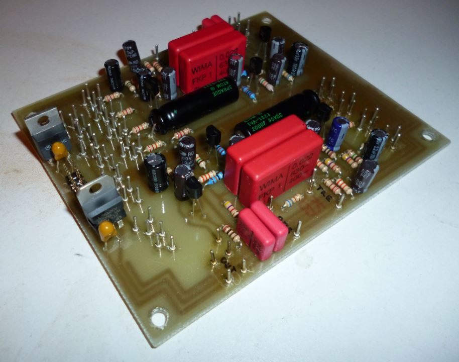
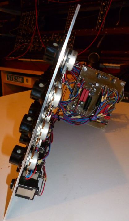
- Board size: 120 x 100 mm
- Left side: Power supply, input distributor
In contrast to the original concept of the Moog modulars I supplied the board with a +/-15V power supply. Voltage regulators on the board convert it to +12V and -6V. Benefit of this is a higher stability of the power supply.
- Lower side: mixer and tone control stage A
- Upper side: mixer and tone control stage B
|
Click to enlarge
|
Click to enlarge
|
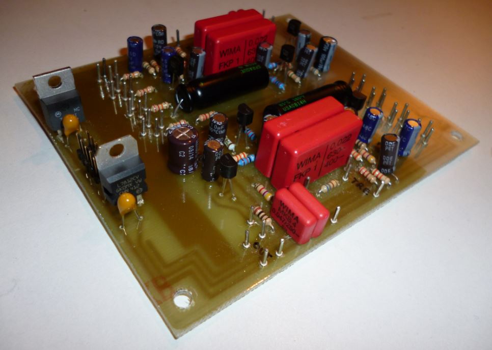
- Board size: 120 x 100 mm
- Left side: Power supply
In contrast to the original concept of the Moog modulars I supplied the board with a +/-15V power supply. Voltage regulators on the board convert it to +12V and -6V. Benefit of this is a higher stability of the power supply.
- Lower side: mixer and tone control stage D
- Upper side: mixer and tone control stage C
|

