Introduction:
Yes, here it is, my first clone of an original Moog module. I decided to clone the 904B voltage controlled high pass filter first because I don't have a pure 4 pole 24db VCHPF yet. And if I don't complete my Moog modular clone I can integrate this module in my other modular projects easily, although a function like this is already implemented in my Formant state variable filter, but only in a 12db implementation which does not work as clean as this Moog version.
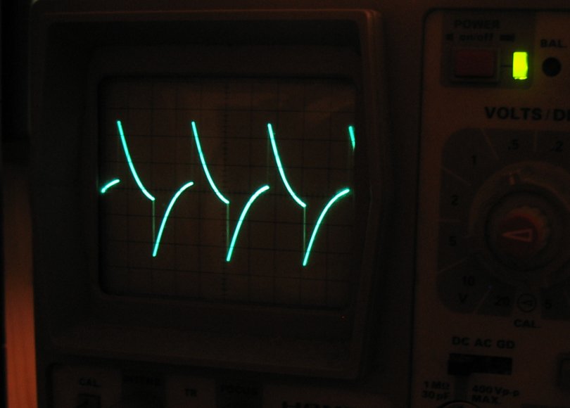
A high pass filter makes a sound more nasal by emphasizing the higher elements of the frequency spectrum. Very nice as sound components for trumpet / brass simulation or similar purposes. One can see this also in oscilloscope pictures (see below), where signal flanks are emphasized until only needles are left (can be heared as very high buzz).
Circuit:
This is a real confusing topic concerning this module. I've found 3 different versions of it yet. One is subtitled with "DATE 6/23/70 DWG. NO 1118". I built a module according to this circuit and it didn't work. Yes, I built a module according to ths schematic, and it didn't work. No, I did not make a mistake during building it, I checked it several times, and it did not work.
I made a spice model of that circuit, and spice also said "No". I compared the simulated voltage processes in the spice model with my real physical one, and both showed the same wrong behaviour.
I lokated the error within the original schematic in the CV mixer section weeks later. The same bug is drawn in my copy of the Moog modular service manual, page 14. This is the second version of the circuit, but also wrong in my opinion. Then I found a third version of the schemo on the web, and this one was ok. I made a spice model of it, and spice said "Yes" this time. I built the module in reality according to the spice model, and it works fine, finally, hurray!
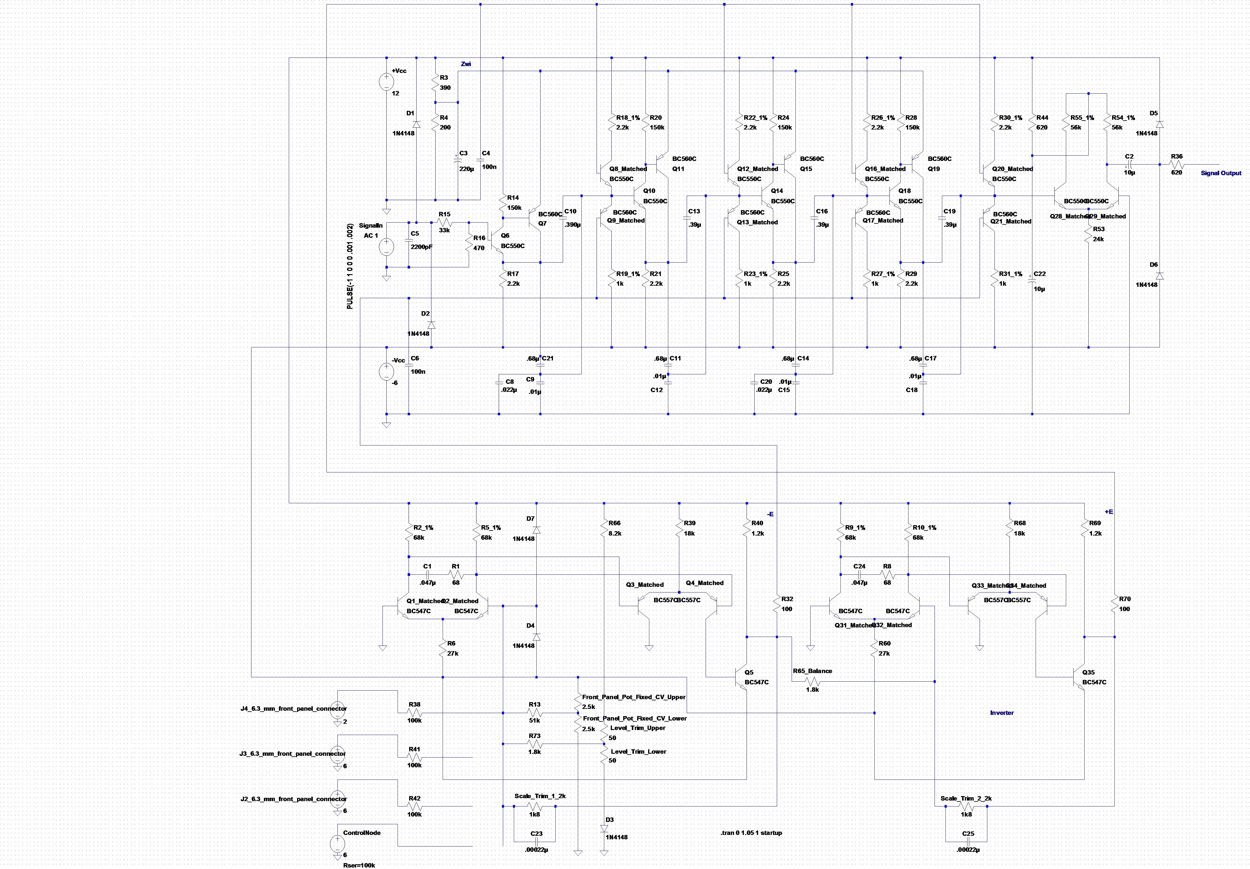
And here you can find my spice model version of the original circuit. Attention: Clicking the circuit means acceptance of the disclaimer on page bottom!
The spice model shows the situation "FREQUENCY RANGE" switch in closed position. Only one control voltage connector is connected to the control node. Trims and pots which work as voltage divider are represented as a set of two resistors.
The lower half of the circuit consists of the control voltage mixer and a following inverter. The incoming control voltages provided by the J2 - J4 connectors, the front panel fixed control voltage pot and the control node of the Moog port are converted into an internal control voltage range of -.45V to -.65V as -E and .45V to .65V as +E (see also original schematics):
The control voltage mixture passes a two stage set of differential amplifiers (Q1, Q2 and Q3, Q4) and is inverted by a collector follower (Q5). The incoming control voltage is low pass filtered by C1 and R1. The feedback trim pot Scale_Trim_1 provides the desired internal control voltage range. It can be adjusted and works like the amplification feedback resisitor of an OpAmp stage. (By the way: this form of control voltage mixture is a standard function of Moog modules and can be found in several other modules, too). The output voltage of the first stage is the input of the internal control voltage inverter stage (via R65), which is constructed identically to the first stage.
The upper half of the circuit consists of the 4 pole voltage controlled high pass filter. The input signal which has to be processed is crushed to an amplitude of 1.4% of the orgininal by the R15 / R16 voltage divider and then fed to the filter pole stages. Each stage consists of a complementary darlington cell (Sziklai pair, e.g. Q6 Q7) and a complementary amplifier (e. g. Q8 Q9). That amplifier works as a voltage controlled resistor and forms a high pass filter in series with a capacitor set (e. g. C8, C9, C10, C21). Two of the capacitors can be decoupled from the circuit by the FREQUENCY RANGE frontpanel switch. This changes the cutoff frequency position of the filter stage from "lower" to "higher" frequency ranges.
As mentioned before 4 filter stages are passed in series. After that an output amplifier recreates the amplitude of the signal to the original value. Here I had to change the circuit totally. The complicated output stage of the original plans did not work (according to spice). In principle this output stage is again a Sziklai cell followed by an emitter follower, but spice didn't get along with it, so I changed this output stage to a simple differential amplifier. This works absolutely fine, also in reality. The output stage has an aplification of about factor 140, so the complete module has an overall amplification of factor 2.
Setup and Test:
I tested the module together with my Formant Modular system. And it works fine. My version of the 904B is able to process the higher signal voltages of the Formant system, not only the lower Moog levels.
The noise level of the T904B is ok. It is better than the noise level of my Formant state variable filter. Unfortunately I can't compare it to an original Moog module, so I can't analyze whether my changes to the circuit had any negative effects on the sound quality, especially my output amplifier primitive. But I don't think so, because the module sounds good.
Some setups have to be done. The Scale trims have to be turned to get the desired internal control voltage ranges (see above). And the same module filter behaviour per octave can be adjusted here.
The Level trim determins where filtering starts related to the input frequency spectrum. I turned it to low level to be able to let a signal pass the module without changes if the Fixed Controlled Voltage front level pot is set to -6. By the way: the values (-6 to 6) printed on the front panel are not the voltages provided by the pot, only the behavioural representation of these voltages.
Part replacements:
I tried to build my module as close to the original as possible, but I had to do some changes due to actual components I use instead of the originals:
- 2n3392 transistor are replaced by BC547C in the control voltage path and by the low noise type BC550C in the audio path.
- 2n4058 transistor are replaced by BC557C in the control voltage path and by the low noise type BC560C in the audio path.
- All diodes are 1N4148
- All resistor and capacity values are changed to values of actual value ranges (e. g. C 200uF => C 220uF)
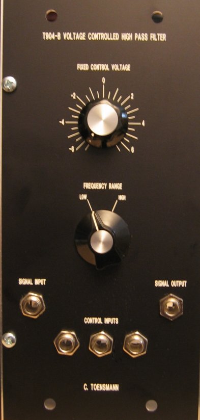
Frontend:
The front panel is designed very generous. It is of double Moog standard size (2 x 2.125"). I don't know why, and nowadays the front panels are more narrow, and also the front panel elements of this module fit on a single size front panel in my opinion. Anyway, the functions of the "human interface" (connectors, switch, pot) of the T904B are identical to the original 904B module. As mentioned above the voltage values engraved around the FIXED CONTROL VOLTAGE knob are a fake, as the potentiometer behind it only provides a subset of these voltages (see schema), but the reaction of the module is the same as if the engraved voltages would have been provided at the control voltage connectors.
The FREQUENCY RANGE switch decouples a subset of the capacitors from the filter section, so the frequency range / cutoff frequency point increases to a higher range.
The 6.3 mm connectors serve as what is engraved above them. No level adjustment pots; this task is done by the 995 attenuator module(s).
Board of the T904B:
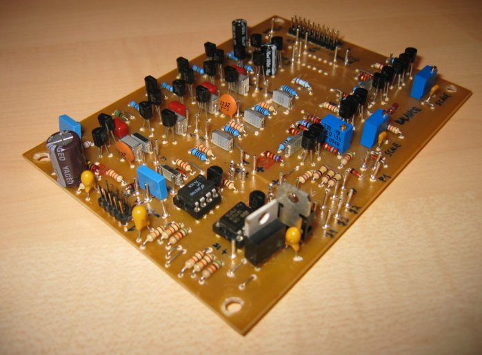
|
|
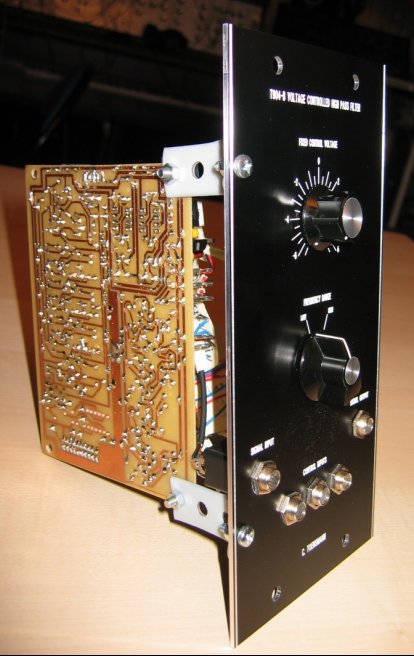
Complete module:
Oscilloscope picture of a high pass filtered pulse 50% duty cycle
Sound example
- Sequence: A slow sine controlling the T904B via CONTROL VOLTAGE input. The T904B processes a short sequence. Pulse waveform with 50% duty cycle. In the second half I tweek the FIXED CONTROL VOLTAGE knob additionally. I added some reverb using my Formant SCR module.