Introduction:
Now this is the second Moog module I've cloned so far. Well, to be honest, this is not a real clone meaning an identical copy, but I built it as close to the orginal as possible. Of course I had to replace the original parts by modern versions, especially transistors, but beside some minor changes I followed the original circuit from the year 1967, when this filter was designed for the famous Moog IIIP system.
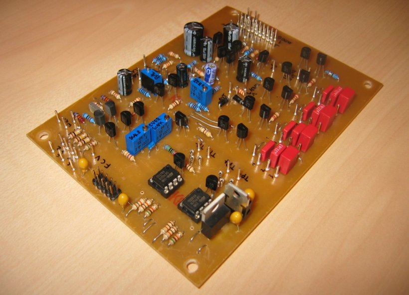
And it is again totally free of integrated circuits (the two opamps you can see on the pics below don't belong to the filter; they serve as part of the Moog transistor matching circuit which I added to the board to be independent of any external test circuit). Unbelievable, after seeing so much filter implementations with integrated circuits which won't exist any more some day I am happy to be able to build filters just with primitives like transistors, capacities and resistors.
The function of a low pass filter is well known, I think, so I will not repeat this here. But this filter has a resonance function which is a difference to the T904B high pass filter I built before. Ok, creating harmonics (upper frequencies) for high pass filter output by resonance does not make real sense in my opinion as a high pass filter creates them directly, but for a low pass filter it can be very interesting to create these harmonics. E. g. if an input signal is low pass filtered and then regenerated you get some odd harmonics which sound a bit like a church organ. Two opposite effects: removing high frequency spectrum by filtering and adding a high frequency spectrum by regeneration. Curious, but it works.
Compared to the filter modules I built for my Fomant Modular the T904A sounds a bit smoother than the ladder filter and a bit more aggressive than the state variable filter. It has its own character, of course, like every other filter implementation.
Circuit:
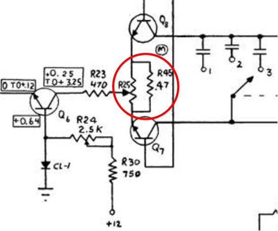 | Ok, this time I was more careful and checked some basic details before I started the development of a spice model. Especially the strange resistor multiturn combination (see picture on the left) in the current sink of the ladder had no measurable effekt on the output signal, so I just omitted it. And this time I had a closer look at the control voltage adder, after the 904B - desaster. But the original schemo of the 904A seems to be ok, and my spice model worked from the beginning. The only thing I had to change was to remove a resistor from the regeneration subcircuit to enable self oszillation.
And here you can find my spice model version of the original circuit. Attention: Clicking the circuit means acceptance of the disclaimer on page bottom! The spice model shows the situation "FREQUENCY RANGE" switch in mid position (2). Only the FIXED CONTROL VOLTAGE pot is connected to the control node. Trims and pots which work as voltage divider are represented as a set of two resistors. |
Mode of operation:
The lower half of the circuit consists of the control voltage mixer and the filter ladder. The upper half consists of the input and the output buffers.
The incoming control voltages provided by the ECV1 - 3 connectors and the fixed control voltage provided by the corresponding front panel pot are mixed in the control node. This voltage mixture is low pass filtered by R5 and C1 and converted into an internal control voltage range from 0 mV to 234 mV by the Q3 Q4 npn and Q1 Q2 pnp differential amplifiers, afterwards inverted by the collector follower Q5. The collector of Q5 is the target node of the ladder current sink (Q6).
The audio input signal provided by the external SIGNAL INPUT jack is buffered by the differential amplifier Q22 and Q23 and feeds the ladder, phase inverted on one side.
The ladder consists of 4 stages (poles, Q7 - Q14) and a pair of current sources (Q15 Q16). Each pole works as a double low pass filter (one per phase), where the capacities are fix (well, 3 fixed values selectable by the FREQUENCY RANGE selector) and the resistors are voltage controlled (transistors), where their behaviour / "resistor value" is determined by the current sink which is controlled by the control voltages (see above). The first pole (Q7 Q8) above the current sink modulates the ladder by the input signal at the bases. The collectors are connected to the emitters of the following pole and so forth. The output signal is decoupled at the collectors of the 4th pole and fed into the output buffer.
The output buffer is "standard old school Moog technology" meaning a double differential amplifier (npn, pnp, Q17, Q19, Q20, Q21) fed by a current source (Q18) and modulated by the output of the ladder. The output signal is fed back into the input circuit via the REGENRATION pot on the one hand and provided phase inverted as the module output on the other hand.
Setup and Test:
Again I tested the module together with my Formant Modular system. After all that theoretical analysis processes the first subjective impression of the real sound and the sound quality was very good. As mentioned above it has its own character, its own sound colour, and I created sounds in the range from "very smooth" to "hardcore fx" just by playing around a little bit with the FIXED CONTROL VOLTAGE and the REGENERATION knobs.
The noise level of the T904A is also ok. It is better than the noise level of my Formant state variable filter. Unfortunately I can't compare it to an original Moog module, so I can't analyze whether my changes to the circuit had any negative effects on the sound quality. But I don't think so, because the module sounds good.
Some setups have to be done. The Scale trims have to be turned to get the desired internal control voltage ranges (see above). And the same module filter behaviour per octave can be adjusted here. And if you setup full resonance without any input signal you can play the module like a sinus oscillator with 1V/oct. behaviour, provided you adjusted the scale trim correctly (well, it is not the most stable oscillator, but it works quite ok).
Module behaviour: The amplification of the audio signal is not constant. I don't know whether the original module acts that way, but a +/- 1V square input for instance will result in a +/-2V output if not filtered. If you add resonance, a frequency spectrum is added, but on maximum regeneration the output amplitude is lowered down to +/- 0.5V output. See the pictures:
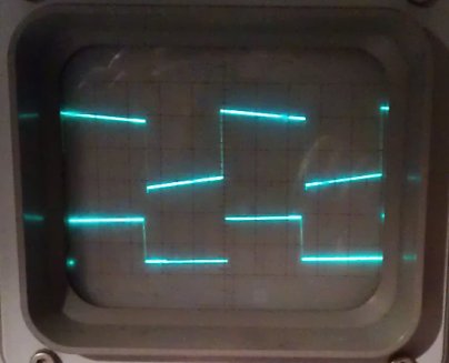
Unfiltered no resonance | 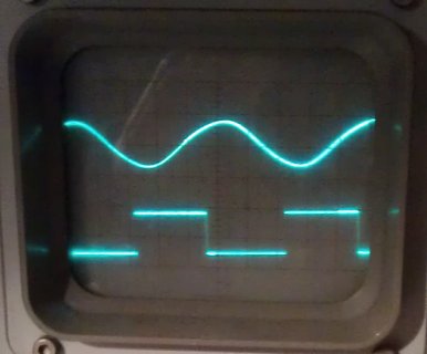
Filtered no resonance | 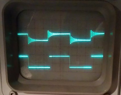
Slightly filtered medium resonance | 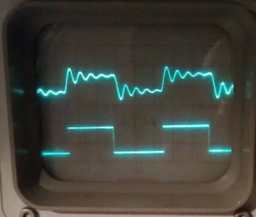
Filtered medium resonance |
Part replacements:
I built my module as close to the original as possible, but I had to do some changes due to actual components I use instead of the originals:
- 2n3392 transistors are replaced by BC547C in the control voltage path and by the low noise type BC550C in the audio path.
- 2n4058 transistors are replaced by BC557C in the control voltage path and by the low noise type BC560C in the audio path.
- All diodes are 1N4148 or 1N4004
- All resistor and capacity values are changed to values of actual value ranges if necessary (e. g. C 200uF => C 220uF)
Frontend:
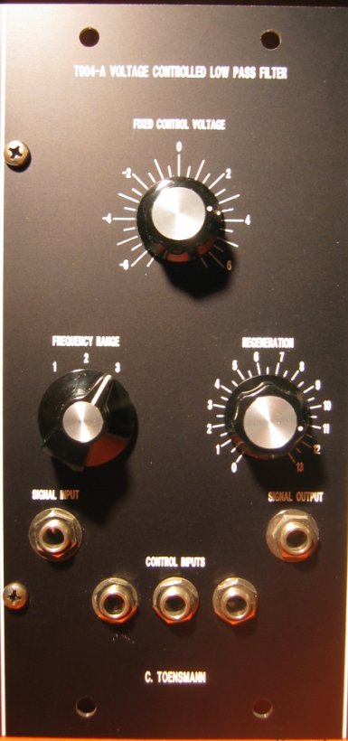
The front panel is designed very generous, like the one from the 904B. It is of double Moog standard size (2 x 2.125"). I don't know why, and nowadays the front panels are more narrow, and also the front panel elements of this module fit on a single size front panel in my opinion. Anyway, the functions of the "human interface" (connectors, switch, pots) of the T904A are identical to the original 904A module. The voltage values engraved around the FIXED CONTROL VOLTAGE knob are a fake, as the potentiometer behind it only provides a subset of these voltages (see schema), but the reaction of the module is the same as if the engraved voltages would have been provided at the control voltage connectors.
The FREQUENCY RANGE switch selects one of three capacitor sets (one per pole, see schema) from the filter section, so the frequency range / cutoff frequency point increases / decreases to other ranges.
The REGENERATION knob controls the amount of feedback of the output signal back to the input. On maximum the T904A works as a sine oscillator, even without input signal, and can be played that way.
The 6.3 mm connectors serve as what is engraved above them. No level adjustment pots; this task is done by the 995 attenuator module(s).
Board of the T904A:
|
|
Setup and test: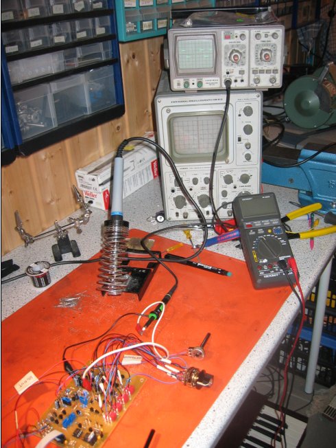
| Complete module: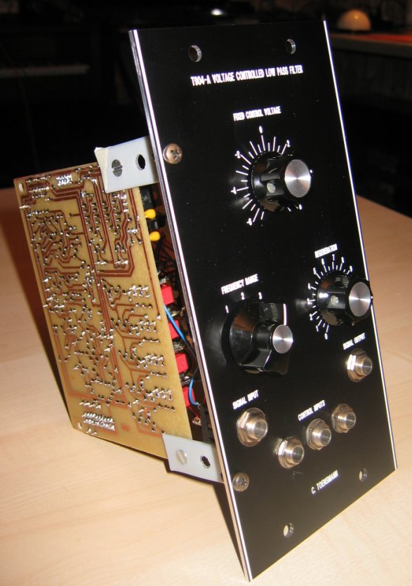
|
Sound examples
- Base Module: A square sequence filtered by an ADSR.
- Moog army: A single square frequency filtered by an LFO. I twiddled with RESONANCE and FIXED CONTROL VOLTAGE. Reverb by my slightly overdriven Formant SCR module.
- Naked Module: No input signal, just the filter in self oscillation mode. I played a little sequence on the keyboard, and the outcomming CV determins the T904A self oscillation frequency. Reverb again by my slightly overdriven Formant SCR module.