
Some keyboard synthesizers like the Memorymoog and some Oberheim synths offer an autotune feature for their (analogue) oscillators. This allows the instrument to tune itself. A certain keyboard or note range is scanned and compared with internal frequency tables to determine a set of control voltage offsets which are used to compensate environmental temperature changes and other reasons for changes in tune or scale.
AFAIK no circuit for modular analogue synthesizers exists up to now to be post-installed as a circuit extension or separate module. Especially the older analogue modulars like the Moog System 55, 35, 15, IIP, IIIP and their reissues have to be retuned due to instrument warm-up, circuit age, environmental changes etc. which can be an annoying process as it is a repetitive and iterative process.
One special candidate for this is the Moog 901ABBB oscillator bank, especially the old originals. The warm-up phase changes tune and scale of the oscillators, so you have to wait a long time before the oscillators are in tune. And from time to time you have to open the instrument to change the scale onboard. This sucks, but people keep this oscillator(s) because of the fantastic warm sound and accept the disadvantages.
I ran into the same problem with my 901ABBB VCO bank clone of my Moog System 55 project, as I cloned it close to the original, especially the exponentiator with all its problems. So I asked myself whether it is possible to gain digital control over the oscillator if you want to play tonal to automatically compensate all those drift effects due to warm-up, age, etc.
So I decided to develop an AUTOTUNE module as stand-alone device to be added to a modular synthesizer as a separate module to take over control over analogue oscillators, to keep them in tune and / or scale automatically without permanent effort of manual re-tuning or re-scaling. AUTOTUNE for everyone, not only for some players of some special keyboards.
The T908:
Basically it is a kind of control and feedback loop, or better to say a kind of regulator circuit. It is able to send and receive MIDI sequences as well as sending and receiving control voltages.
The human interface provides the following I/O:
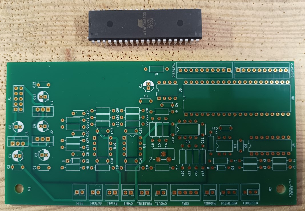
Display: The 2-digit display at the top displays the selected program (run mode) or note data (note and octave).
Trigger: The three trigger buttons control the module: With "SET" you select the program the T908 should perform. With "ENTER" the selected program / run mode is invoked. With "RESET" the T908 performs a basic initialization / module reset.
3.5 mm connectors: At the "PULSE IN" input jack bush the triangle signal of the oscillator-to-tune is fed in. At the "CV IN" input jack bush control voltages to be analyzed can be fed in in general. The "CV OUT" jack bush provides the offset voltage to tune the oscillator-to-tune.
5 pole DIN connectors: The "ISP" connector serves to upload software / firmware / the T908 OS. "MIDI IN" tells the T908 which note has to be tuned or better to say which oscillator output frequency is expected. "MIDI THRU" is needed for MIDI cascading. "MIDI OUT" provides the MIDI seqences for the MIDI2CVGATE interface to perform an autotune full run.
Run modes:
Currently the following run modes can be invoked:
- P1
"AUTOTUNE Full Run": This is the default mode which is invoked after module power-on or reset. When pressing "ENTER" a full run is invoked. This means that the T908 sends MIDI commands for each note of a 5 octave keyboard, starting at c0, c#0, d0, d#0 etc. 12 semitones per octave up to c5.
Tuning process: The output frequency of the oscillator-to-tune is scanned by the T908 using the "PULSE IN" input jack. A wave cycle is measured in time and the result is compared to an internal frequency lookup table entry for the corresponding note. From the deviation a delta CV offset is derived from the T908 and provided at the "CV OUT" jack. This is added to the oscillator control voltage of the MIDI interface which changes the oscillator output frequency obviously. The new frequency is scanned again, the CV offset is adapted etc. until the incoming oscillator frequency fits perfectly to the frequency lookup table.
After the tuning of the note the T908 tunes the next note until c5 is completed. All detected CV offsets are stored in an internal list and are used as base for auto correction during your play in "P2" or "P3" mode.
- P2
"AUTOTUNE Online Mode": This mode does a permanent autotuning during your play. When pressing "ENTER" the T908 invokes a tune process for each note which is played on the keyboard. The newly detected correction of the correction overwrites the old CV offset within the internal memory correction list, so changing drifts of the oscillator due to e.g. warm-up effects of the oscillator are compensated "online" without the necessity of a new full run.
The tuning for the note is performed as described for "P1".
- P3
"AUTOTUNE Offline Mode": This mode performs an autotune for each note being played according to the current values of the internal memory CV offset list. In this case the auto correction is fix and is not changed during your play. This is the way the Memorymoog and some Oberheim synths perform, AFAIK. This mode is needed for e.g. portamento usage.
- P4
"SAVE EEPROM": This function writes the CV offset list which is currently in use from program memory to EEPROM for permanent storage.
- P5
"LOAD EEPROM": This function loads the CV offset list which shall be used from EEPROM to program memory.
P4 and P5 avoid the necessity of doing another AUTORUNE Full Run after a system reset or power down of the module.
T908 Schema:
T908 schema Clicking the schema means acceptance of the disclamer on page bottom!
Power supply: The T908 is connected to the PSU bus of the modular system which provides +/-18V for the module. All needed operating voltages are derived from that by voltage regulators. The T908 operates with +/-12V and +5V.
CPU: Core of the T908 is my favorite microcontroller Atmel ATmega8535. It is configured to run with the internal 8Mhz oscillator by corresponding fuses. May not to be changed during new firmware upload processes!
Display: The current module version works with two 7-segment displays with dot and common ground. All segments and the dots are directly addressed by the CPU. The ground connections of the displays are done via 2k2 resistors (r30,r31,r32, r33) to reduce the power consumption of the CPU.
Trigger: These are simple short-to-ground trigger. The "SET" and "ENTER" trigger cause a voltage drop at the corresponding CPU pin when pressed (via r20 and r25). Debouncing is done via the lowpass filters r21 C19 and r27 C20.
The "RESET" trigger performs a CPU reset via r8, C8 and D2. It is also connected to the ISP interface.
Jack bush connectors: The input connectors "PULSE IN" and "CV IN" are buffered with two inverting buffers per channel (U9, U10) and provided at corresponding CPU ADC input pins. The "CV OUT" connector provides the output control voltage offset created by the CPU via the serial DAC U5 and the two inverting output buffers U6. C21 reduces digital noise and artefacts. With Tr1 the output voltage amplification is adjusted.
ISP DIN connector: All Analogmonster projects which use a microcontroller provide an ISP connector for uploading firmware during development and future firmware upgrades. Please refer to the Atmel documentation for further information.
MIDI IN DIN connector: This is a standard current-loop interface for connecting galvanic isolated devices. The incoming serial MIDI protocol is passed via r1 and D1 to the opto coupler U1. The receiver side is connected to the RXD serial interface pin of the CPU. R7 works as pull-up resistor for RXD.
MIDI THRU DIN connector: The incoming RXD signal from MIDI IN is buffered via U4 and is provided as current source for MIDI cascading via r2 and r3.
MIDI OUT DIN connector: Serial MIDI communication (TXD) which is initiated by the T908 (e.g. AUTOTUNE Full Run) is buffered by U4 and is provided as current source for other MIDI devices (e.g. MIDI2CVGATE interfaces).

T908 hardware

| 
|
| 
|
YouTube

T908 Demo of Workbench test: Autotune Full Run of the prototype

T908 Demo 1: Workbench test: Autotune Full Run and octave demo