Intro:
This module has been on my wish list for a long time. Just using it in the standard configuration (controlling a VCF with the CV output of the S&H module) is a sound I like very much. But there are much more possibilities of course.
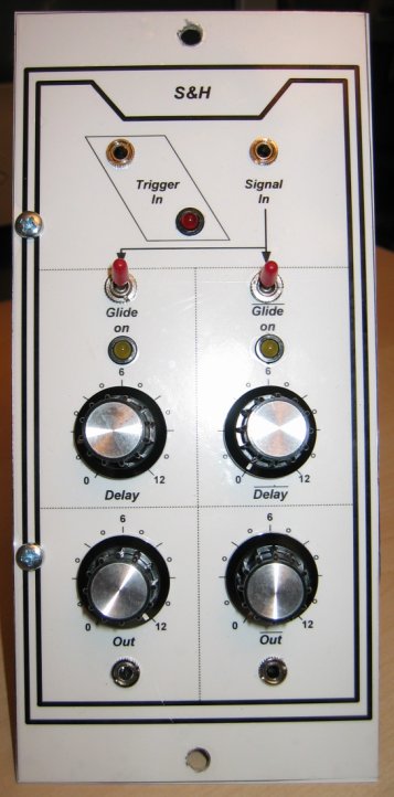
Frontend:
The samples are taken from the input signal connected at 'Signal In'. This can be anything, e. g. a LFO output, a random voltage of a noise module, any audio signal of a VCO or white noise.
The sample time is about 10”s.
The sample process is startet by a trigger pulse or clock signal at 'Trigger In'. These pulses are also made visible with the red trigger LED.
The sampled voltage is amplified by 2.2 and divided on two signal paths, one of them with inverting input. The result is two 'oppositional' voltages provided at 'Out' and '/Out', each controllable by a range pot.
Additionally each signal path has a 'Glide' / portamento function which is selected by the glide switch (with control LED) which smoothes the hard CV jumps of the S&H output according to the 'Delay' pot.
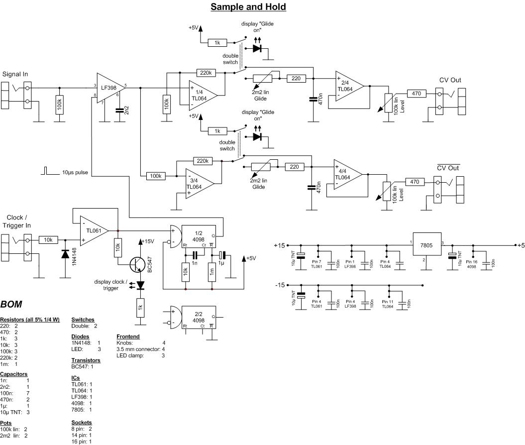
Circuit:
The module is built around an LF398 Sample and Hold chip.
The rising edge of the clock- / trigger signal (0V => 5V) triggers a 4098 monoflop which sends a 10”s 5V pulse to the sample control input of the LF398 which stores the input signal voltage in a hold capacitor during this time. After termination of the sample pulse the signal voltage value is kept by the capacitor.
The output of the LF398 is given to a pair of opamps for each signal path. On one signal path the first opamp works as an inverting amplifier, on the other signal path it is a non inverting one. According to the 'Glide' switch position the output voltage passes a portamento circuit (pot plus capacity) or is connected directly to the output buffer stage (2nd opamp of the signal path).
As I wanted to display the current glide selection optically I used a double switch for glide activation. The other swich is used to switch on the control LED.
To let the 4098 start in a defined behaviour I implemented a chip reset of one second (1m resistor and 1” capacity).
And here is the circuit. Attention: Clicking the circuit means accepting the disclaimer on page bottom!
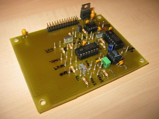
Board of Sample and Hold module:
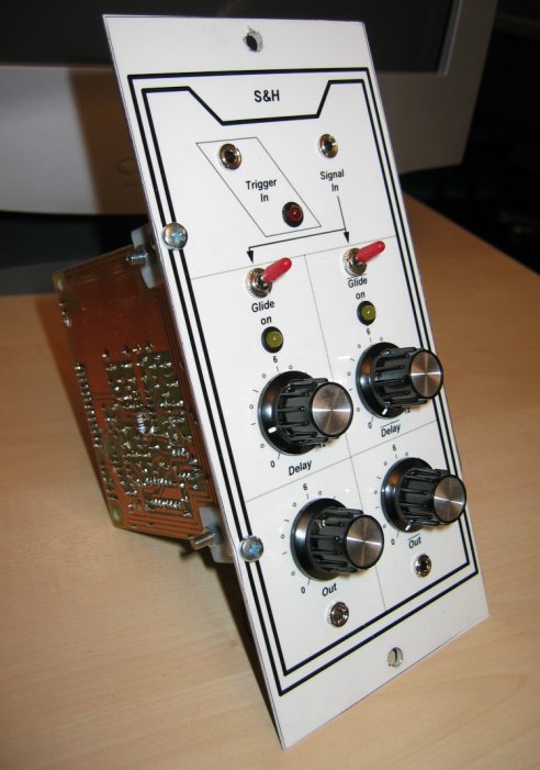
Complete module:
Sound examples:
1.) Patch 1: S&H - Modul controls VCF
2.) Patch 2: S&H-Out controls VCF, S&H-/Out with slight glide controls directly and by mixer and CVS once again inverted via two VCAs the stereo output channels. The result has been sent thru the 'chorus 2' function of the SCR.
Construction hints:
If I build this module again I will provide a level pot for 'Signal In'.
The storage capacitor for the samples should be a low leakage type (please refer to the LF398 data sheet, please see also the application hints there).
The unused half of the 4098 should be reset connecting the corresponding pin to ground permanently (see also application hints of 4098).