Click to enlarge
Click to enlarge
Click to enlarge
Click to enlarge

Click to enlarge | Click to enlarge | Click to enlarge | Click to enlarge |
|
|
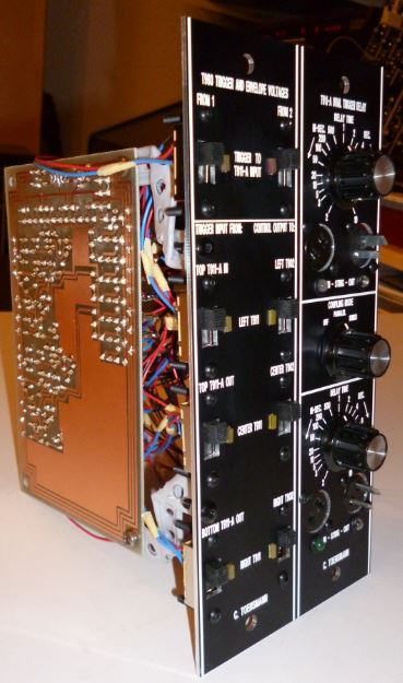
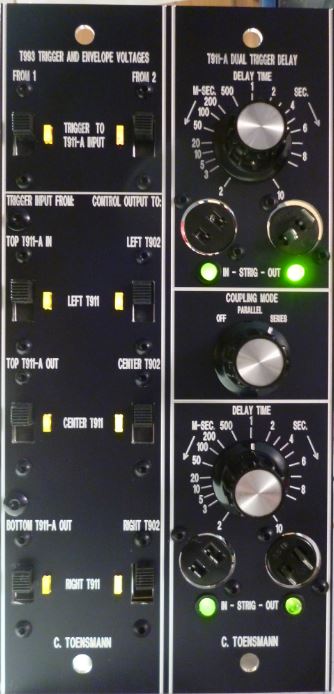
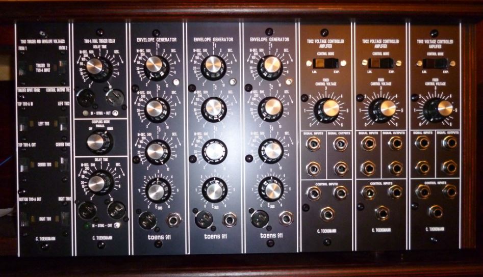
T993 Trigger Envelope Voltage Router The two switches on top of the front panel determine which incoming STrigger event is processed. The module can handle two STrigger events, so there are two switches. As the label says the STrigger events - if switched on - are routed to the input of the top unit of the T911-A Dual Trigger Delay on the right. The left switch of the second row routes the incoming STrigger events mentioned above to the left envelope generator (see functional unit above) at the same moment. The left switch of the third row routes the (delayed) output trigger event of the top delay unit to the center EG. The left switch of the fourth row routes the output of the lower delay unit of the T911-A to the right EG module. The right switch of the second row routes the resulting envelope voltage of the left EG to the left VCA (see functional unit above). The right switch of the third row routes the resulting envelope voltage of the center EG to the center VCA. And the right switch of the fourth row routes the resulting envelope voltage of the right EG to the right VCA. All sources and targets are labeled on the front panel. T911-A Dual Trigger Delay On the top of the front panel one can find the first STrigger delay unit. The potentiometer determines the delay time until the incoming trigger event is forwarded to the output. LEDs indicate the incoming and outgoing STrigger event. The T911-A can be used without the T993 router, for this purpose the Cinch Jones connectors can be used as input (female) and output (male) terminals for the STrigger events. The second delay unit works identically. In the center of the front panel the coupling mode of the two delay units can be determined. "OFF" means that no coupling is done, "PARALLEL" means that both delay units are fed with the same STrigger input event, and "SERIES" means that the second delay unit is fed by the output of the first one. Example A nice effect can be achieved if the two delay units are coupled in "SERIES" mode and the keyboard STrigger event is routed to the first EG/VCA combination which controles the sound amplitude, the delayed output of the first delay unit is routed to the second EG which controls a T904-A VCF, and the delayed output of the second delay unit is routed to the third EG which controles the pitch of the sound. If you press a key the sound starts unmodulated, after a short time the VCF starts to modulate the sound and after another short time period the pitch of the sound rises. A (delayed) sequence of modulation events like this is very important in electronic music, much more than starting complex modulations at the same time. |
|
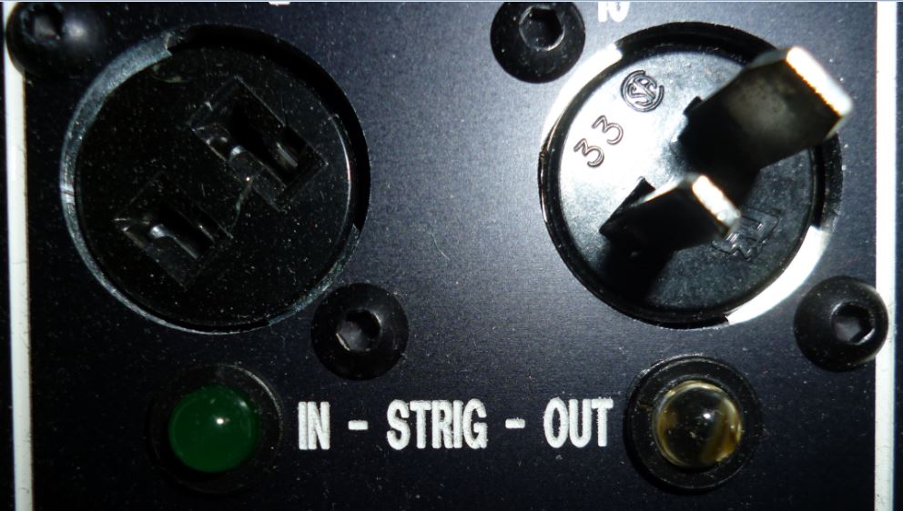
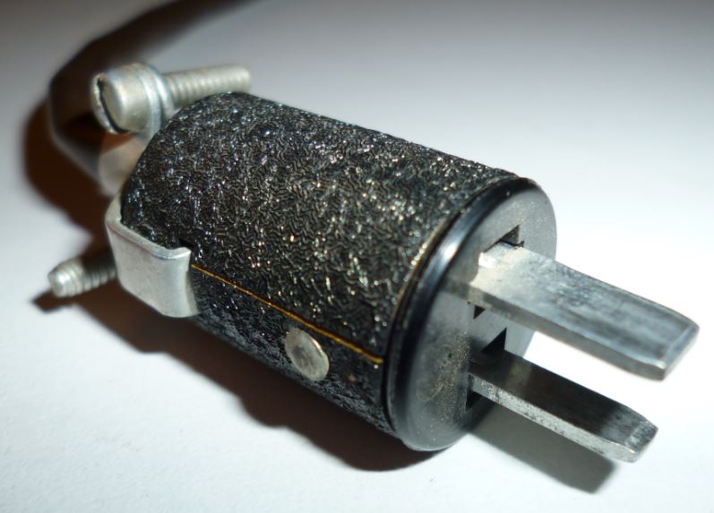
Cinch Jones jack and plug The gate event of a key beeing pressed on the keyboard or of a step of a sequencer is beeing reached follows a different concept in many older Moog synthesizers, inclusive the modular systems, compared to other synthesizer systems. Other synthesizer manufacturers and modular systems use a so called "gate" event which is physically spoken a binary control voltage of 0V (gate off) and somewhat between 5 to 10V (gate on). This control voltage is not handled separately from other control voltages and can be used for other purposes than note playing also. The Moog concept differs. The "gate" event is not represented as a voltage but as a current sink (STrigger) and therefore should not be mixed with other control voltages. To prevent an accidental connection between signals, control voltages and the STrigger event no 1/4" phone plugs are used to submit the gate event to corresponding modules but so called 2-pole Cinch Jones jacks and plugs. The Cinch Jones jack serves as input for STrigger events, the plug as output. The 2-pole Cinch Jones connector contains two blades of different width on the plug side and the corresponding females on the jack side (see pictures). As the STrigger concept is a current sink, only one pole would be necessary to transmit the event. This is done via the smaller blade. The wider blade works only as ground reference for the connected modules, not as shield like in phone plugs. |
|
|
 Click to enlarge |
 Click to enlarge |